background image

Maintenance 

34

3A9019A EN

Maintenance

Routine maintenance is important to ensure proper operation of your sprayer. 
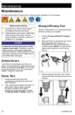
Airless Hoses

Check hose for damage every time you 

spray. Do not attempt to repair hose if hose 

jacket or fittings are damaged. Do not use 

hoses shorter than 25 ft. (7.6 m). Wrench 

tighten, using two wrenches.

Spray Tips

Always clean Spray Tips with 

compatible cleaning fluid and brush 

after spraying.

Tips may require replacement after 15 

gallons (57 liters) or they may last 

through 60 gallons (227 liters) 

depending on abrasiveness of paint. 

See 

Spray Pattern Quality

, page 20

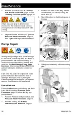
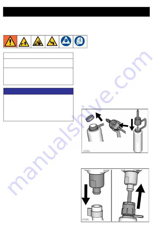
Storage/Priming Tool

Perform these steps if you are experiencing 

difficulty priming your sprayer.

1. Perform 

Pressure Relief Procedure

page 15.

2. Remove Pump Armor bottle cap. Insert 

small fluid tube into bottom of 

Storage/Prime Tool, and thread tool 

onto the bottle. 

NOTE:

 For best results, 

make sure the bottle is full of Pump 

Armor.

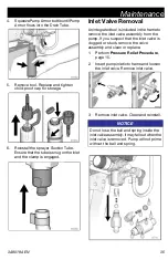
3. Remove sprayer Suction Tube. Insert 

tool into the inlet and push up firmly until 

it stops.

Maintenance Activity

1. Inspect motor shroud openings for 

blockage every time you spray.

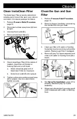
2. Clean/inspect inlet screen, InstaClean 

filter, and gun filter every time you 

spray. Replace if the filter cannot be 

cleaned or is damaged. 

NOTICE

Protect the internal drive parts of this 

sprayer from water. 

Openings in shroud 

allow cooling of mechanical parts and 

electronics inside. If water gets into these 

openings, the sprayer could malfunction or 

be permanently damaged.

Summary of Contents for PROX19

Page 1: ...t Be familiar with the controls and the proper usage of the equipment Save these instructions 888 541 9788 http magnum graco com magop Magnum Products Operational Videos http magnum graco com magop For portable spray applications of architectural paints and coatings only Not approved for use in explosive atmospheres or hazardous classified locations ...

Page 2: ...0V 6ah DCB609 60V 3ah 20V 9ah DCB612 60V 4ah 20V 12ah Related DEWALT Manuals 312830 SG Spray Guns 3A3172 ProXChange Pump Charger Voltage VAC Model Cart 120 ProX19 25U478 CAN478 110474 Certified to CAN CSA C22 2 No 68 Conforms to UL 1450 Visit Our Website magnum graco com Operational Videos magnum graco com magop Manuals magnum graco com support manuals Parts Online magnum graco com partsonline Man...

Page 3: ... Pump Prime Pump 17 Fill Gun and Hose 18 Refill Paint Pail 19 Blockages 19 Spraying 20 Start 20 Adjust Pressure Control 20 Spray Pattern Quality 20 Spray Techniques 21 Trigger the Gun 21 Aim Gun 21 Align Spray Pattern 21 Spray Tip and Pressure Selection 22 Clear Spray Tip Clog 23 Spray Tip Installation 23 Cleanup 25 Clean from a Pail 25 Cleanup with Power Flush Valve 27 Clean InstaClean Filter 29 ...

Page 4: ... Inlet Valve Removal 35 Pump Repair 36 Troubleshooting 38 ProX19 Cordless Cart Sprayer Parts 43 ProX19 Cordless Cart Sprayer Parts List 44 ProXChange Pump Parts 45 ProXChange Pump Parts List 46 Wiring Diagram 60VDC 47 Technical Specifications 48 Graco Standard Warranty 49 Graco Information 50 ...

Page 5: ...amp Required Type of Material WATER BASED The container label should indicate that the material can be cleaned up with soap and water OIL BASED The container label should indicate that the material is COMBUSTIBILE and can be cleaned up with mineral spirits or non flammable paint thinner Use oil based material outdoors or in a well ventilated indoor area with a flow of fresh air See the safety warn...

Page 6: ...ot operate light switches engines or similar spark producing products in the spray area Keep area clean and free of paint or solvent containers rags and other flammable materials Know the contents of the paints and solvents being sprayed Read all Safety Data Sheets SDSs and container labels provided with the paints and solvents Follow the paint and solvent manufacturer s safety instructions Keep a...

Page 7: ...0 7 MPa Always engage the trigger lock when not spraying Verify the trigger lock is functioning properly Verify that all connections are secure before operating the unit Know how to stop the unit and bleed pressure quickly Be thoroughly familiar with the controls EQUIPMENT MISUSE HAZARD Misuse can cause death or serious injury Always wear appropriate gloves eye protection and a respirator or mask ...

Page 8: ...oth moistened with water MOVING PARTS HAZARD Moving parts can pinch cut or amputate fingers and other body parts Keep clear of moving parts Do not operate equipment with protective guards or covers removed Equipment can start without warning Before checking moving or servicing equipment follow the Pressure Relief Procedure and disconnect all power sources TOXIC FLUID OR FUMES HAZARD Toxic fluids o...

Page 9: ... L Gun Fitting M Gun Filter inside handle N ProXChange Pump behind Easy Access Door O Inlet Valve P Airless Hose Connection Q Airless Hose R InstaClean Filter inside fluid outlet S Pail Hanger T Inlet Screen U Battery V Easy Access Door X Pump Removal Tool Y Outlet Valve Z Inlet Valve Removal Tool AA Battery Cover AB Ground Wire w Clamp AC Outlet Ground Adapter Model Serial Tag Not shown located o...

Page 10: ...ither the Drain Tube or the hose and gun It is used to prime the sprayer which means to evacuate the air out of the pump hose and gun Your gun will not spray if there is air in the system It is necessary to prime the pump hose and gun any time air enters the Suction Tube The Spray Tip is the key to airless spray technology High pressure paint pumped through the very small hole in the Spray Tip com...

Page 11: ... outlet use a 3 wire grounded extension cord between the adapter and outlet Fluid hoses Use only electrically conductive hoses with a maximum of 300 ft 91 m combined hose length to ensure grounding continuity Spray gun Grounded through connection to a properly grounded fluid hose and pump To maintain ground continuity when sprayer is flushed or pressure is relieved hold metal part of gun firmly to...

Page 12: ...ire to the pail Clamp one end to the pail and the other end to a true earth ground such as a water pipe To maintain ground continuity when sprayer is flushed or pressure is relieved hold metal part of spray gun firmly to the side of a grounded metal pail then trigger the gun ti24584a ...

Page 13: ...wrenches when connecting the hose to the gun both for ease of installation and to ensure a tight connection If hose is already connected make sure connections are tight 3 Assure Spray Tip is properly inserted into the Spray Tip Guard and the Spray Tip Guard assembly is tightened securely to gun See Spray Tip Installation page 23 To avoid serious injury from skin injection do not put your hand in f...

Page 14: ...ayer Remove and install battery into the sprayer as follows 1 Remove the used battery if in place 2 Install battery by aligning the battery packwiththe rails inside the sprayer and sliding it in until the battery pack is firmly seated Ensure that it does not disengage Replace and charge battery only in a well ventilated area and away from flammable or combustible materials including paints and sol...

Page 15: ...n to PRIME position to relieve pressure 5 Hold the gun firmly to a pail Point gun into pail Disengage the trigger lock and trigger the gun to relieve pressure 6 Engage the trigger lock 7 If you suspect that pressure has not been fully relieved see Blockages page 19 NOTE Leave Prime Spray Valve in the PRIME position until you are ready to spray This equipment stays pressurized until pressure is man...

Page 16: ...f spraying oil based or flammable material When flushing oil based or flammable materials follow Grounding Instructions page 11 4 Turn Prime Spray Valve down to PRIME position 5 Install battery see Battery Installation and Removal page 14 6 Press the PushPrime button twice to loosen Inlet Valve ball 7 Align setting indicator with the START setting on the pressure control knob 8 Turn ON OFF switch ...

Page 17: ...t strainer bag over a clean pail and pour the paint through the strainer Fill Pump Prime Pump The Prime Spray Valve directs the fluid to either the Drain Tube or the hose and gun It is used to prime the sprayer which means to evacuate the air out of the pump hose and gun Your gun will not spray if there is air in the system It is necessary to prime the pump hose and gun any time air enters the suc...

Page 18: ...illuminated when ON 3 Trigger gun into waste pail until only paint comes out of the gun 4 Release trigger Engage trigger lock NOTE Inspect for leaks If leaking occurs perform Pressure Relief Procedure page 15 then tighten all fittings and repeat Fill Pump Prime Pump page 17 5 Transfer Drain Tube to paint pail and clip to Suction Tube 6 Rotate Spray Tip back to SPRAY position and ensure the Spray T...

Page 19: ...If paint does not come out of the gun or if you have performed the pressure relief pro cedure and you suspect pressure has not been fully relieved 1 VERY SLOWLY loosen the hose connection to the gun and disconnect the airless spray hose from the gun 2 Turn Prime Spray Valve horizontal to SPRAY position 3 While holding hose firmly point end of hose into paint pail and turn ON OFF switch to ON posit...

Page 20: ... cardboard 3 If needed increase Pressure Control Knob setting to minimum setting that results in an acceptable spray pattern Spray Pattern Quality A good spray pattern is evenly distributed as it hits the surface Spray should be atomized evenly distributed no gaps at edges Increase Pressure Control Knob setting if needed until spray is even and without gaps at edges Spray Tip may be wornor a small...

Page 21: ...ger the Gun Pull trigger after starting stroke Release trigger before end of stroke Gun must be moving when trigger is pulled and released Aim Gun Aim center of spray of gun at bottom edge of previous stroke overlapping each stroke by half Align Spray Pattern 1 Relieve pressure Perform Pressure Relief Procedure page 15 Engage trigger lock 2 Align guard horizontally to spray a horizontal pattern 3 ...

Page 22: ...Narrow spray fan for smaller projects Wider spray fan for larger projects Tip Number Calculation The first digit is half of the fan width 5 x 2 10 inch fan width The last twodigits are the size of the tip opening in thousandths of an inch As you spray the Spray Tip wears and as a result the hole size gets larger Starting with a Spray Tip hole size smaller than the maximum will allow you to spray l...

Page 23: ...ficult to rotate when turning to the UNCLOG position perform Pressure Relief Procedure page 15 then turn Prime Spray Valve horizontal to SPRAY position and repeat step 1 2 Engage trigger lock Rotate Spray Tip back to SPRAY position Disengage trigger lock and continue spraying Spray Tip Installation To prevent Spray Tip leaks make certain Spray Tip and Spray Tip Guard are installed properly 1 Perfo...

Page 24: ...eal in the Spray Tip Guard b Spray Tip must be pushed all the way into the Spray Tip Guard Rotate Spray Tip while pushing down c Turn the arrow shaped handle on the Spray Tip forward to the SPRAY position 4 Screw Spray Tip Guard assembly onto the gun and tighten ...

Page 25: ...rd assembly from gun and place in waste pail 4 Lift Suction Tube and Drain Tube from paint pail Let paint drain into the pail 5 Separate Drain Tube smaller from Suction Tube larger 6 Place empty waste and flushing fluid pails side by side 7 Place Suction Tube in flushing fluid For water based paints use water For non water based paints use mineral spirits paint thinner or compatible flushing fluid...

Page 26: ... b Pull and hold gun trigger B c Turn Prime Spray Valve horizontal to SPRAY position C d Turn ON OFF switch to ON position D Button is illuminated when ON e Continue to hold gun trigger until you see paint diluted with flushing fluid starting to come out of gun 15 While continuing to trigger gun quickly move gun to redirect spray into waste pail Continue triggering gun into waste pail until flushi...

Page 27: ...included with sprayer to garden hose Close Power Flush Valve 8 Turn on water Open Power Flush Valve Rinse paint off Suction Tube Drain Tube and inlet screen Close Power Flush Valve 9 Unscrew inlet screen from Suction Tube Place inlet screen in waste pail Connect garden hose to Power Flush Valve on Suction Tube Leave Drain Tube in waste pail 10 Install battery see Battery Installation and Removal p...

Page 28: ...ing fluid starting to come out of gun 16 While continuing to trigger gun quickly move gun to redirect spray into waste pail Continue triggering gun into waste pail until flushing fluid dispensed from gun is relatively clear 17 Turn pressure control knob to the lowest setting 18 Stop triggering gun Engage the trigger lock 19 Turn Prime Spray Valve down to PRIME position 20 Turn ON OFF switch to OFF...

Page 29: ... C in sprayer b Screw fluid outlet B into sprayer 6 Tighten outlet valve and reconnect hose A to sprayer Use two wrenches to tighten securely Clean the Gun and Gun Filter 1 Perform Pressure Relief Procedure page 15 2 Remove the gun handle by unscrewing the handle from the gun head 3 Clean gun filter with water or flushing fluidand a brush every time youflush the system Replace gun filter if damage...

Page 30: ...n attached to hose 6 Remove Spray Tip and Spray Tip Guard and clean with water or flushing fluid and a brush 7 Wipe paint off outside ofgunusinga soft cloth moistened with water or flushing fluid Long Term Storage more than 2 days Pump ArmorTM fluid protects the sprayer against freezing and corrosion Do not store the sprayer full of water Do not allow water to freeze in sprayer Do not store spraye...

Page 31: ...and turn Power Switch ON Button is illuminated when ON 7 When Pump Armor is flushed through the sprayer and out the Drain Tube turn Power Switch OFF Replace and tighten child proof cap for storage 8 Screw Inlet Screen back to Suction Tube Ensure that spray gun and hose stay attached to sprayer 9 Turn Spray Prime Valve horizontal to SPRAY position for storage 10 Turn ON OFF switch to OFF position B...

Page 32: ...s after spraying oil based or flammable materials and flushing with mineral spirits or compatible solvents flush the system thoroughly with water first The water flowing out of drain tube should be clear and solvent free before you begin spraying the water based material To spray oil based or flammable materials after spraying water based materials and flushing with water flush the system thorough...

Page 33: ...ering spray gun to reduce Spray Tip clogs N ProXChange Pump Pumps and pressurizes fluid and delivers it to Airless Hose O Inlet Valve Allows paint to flow from paint bucket into the sprayer P Airless Hose Connection Threaded connection for airless hose Q Airless Hose Transports high pressure fluid from pump to spray gun R InstaClean Filter Filters fluid coming out of pump to reduce Spray Tip clogs...

Page 34: ... are experiencing difficulty priming your sprayer 1 Perform Pressure Relief Procedure page 15 2 Remove Pump Armor bottle cap Insert small fluid tube into bottom of Storage Prime Tool and thread tool onto the bottle NOTE For best results make sure the bottle is full of Pump Armor 3 Remove sprayer Suction Tube Insert tool into the inlet and push up firmly until it stops Maintenance Activity 1 Inspec...

Page 35: ...is included in the frame to remove the inlet valve assembly from the pump If you suspect that the inlet valve is clogged or stuck remove the valve assembly and clean or replace 1 Perform Pressure Relief Procedure page 15 2 Insert pump inlet into frame and loosen the inlet valve Remove inlet valve 3 Remove inlet valve Clean and reinstall NOTICE Do not lose the ball and spring inside the inletvalve ...

Page 36: ...s replaced check pump inlet and outlet valves for wear or damage Replace if worn or damaged Always replace inlet and outlet valves every second time the pump kit is replaced Pump Removal Remove airless hose suction tube and drain tube Always perform Pressure Relief Procedure page 15 before starting any pump repairs 1 Perform Pressure relief procedure see Pressure Relief Procedure page 15 1 Remove ...

Page 37: ...y onto the mounting pins a Move pump rod up or down until cap is level with the opening in the yoke b Push on pump rod to slide pump assembly back on to mounting pins 2 Swing Easy Access Door closed while pushing the entire door down 3 Install hose suction tube and drain tube 4 Install battery see Battery Installation and Removal page 14 NOTE Door must be fully closed and latched before sprayer wi...

Page 38: ...rol is set at zero pressure Turn pressure control knob clockwise to increase pressure setting Battery has insufficient charge Charge battery Battery is defective Replace battery Pump is seized Paint has hardened in pump or water is frozen in pump Turn ON OFF switch off and remove battery If frozen do NOT try to start sprayer until it is completely thawed or it may damage the motor control board an...

Page 39: ... loosen inlet valve and reprime sprayer See Fill Pump Prime Pump page 17 See Storage Priming Tool page 34 Then reprime pump Remove inlet and or outlet valves and clean replace and reprime See Fill Pump Prime Pump page 17 Make certain to not lose the ball and spring of the inlet valve assembly or the sprayer will not function See Inlet Valve Removal page 35 Make certain the outlet ball moves free i...

Page 40: ...ssing Replace gasket and seal See Spray Techniques page 21 Inlet screen is clogged or Suction Tube is not immersed in paint Clean debris off inlet screen and make sure Suction Tube is immersed in paint Battery has insufficient charge for tip support Charge battery or reduce tip size Inlet valve or outlet valve is worn or clogged with debris Check for worn or contaminated inlet valve or outlet valv...

Page 41: ...e worn Replace pump See Motor is hot and runs intermittently Motor automatically shuts off due to excessive heat Damage can occur if cause is not corrected Vent holes in enclosure are plugged or sprayer is covered Keep vent holes clear of obstructions and overspray and keep sprayer open to air Battery has insufficient charge Charge battery Motor needs to be replaced Take sprayer to Graco Magnum au...

Page 42: ...fully charged or replace battery Control board is damaged Replace control board Power switch is damaged Replace power switch ON OFF switch is constantly illumi nated does not turn off Control board is damaged Replace control board Problem Cause Solution Visit Our Website magnum graco com Operational Videos magnum graco com magop Manuals magnum graco com support manuals Parts Online magnum graco co...

Page 43: ... Cordless Cart Sprayer Parts Ref Torque Ref Torque 110 120 in lb 12 14 N m 23 27 in lb 2 6 3 0 N m 30 35 in lb 3 5 4 0 N m 80 90 in lb 9 10 2 N m 8 10 in lb 0 9 1 2 N m 180 220 in lb 20 3 24 0 N m 45 55 in lb 5 6 N m 55 65 in lb 6 2 7 3 N m 1 5 2 6 3 7 4 8 ...

Page 44: ...73 TUBE suction assembly includes 26a 26b 26c 26d 26e 26f 26g 26h 1 26a 16H348 TUBE suction includes 26b 1 26b 115099 WASHER hose 1 26c 288716 STRAINER inlet 1 26d 244035 DEFLECTOR barbed 1 26e 115489 CLAMP drain tube 2 26f 195400 CLIP spring 1 26h 116295 CLAMP tube 1 26g 195108 TUBE drain 1 27 17J819 PLUG hole 1 in 1 28 16D576 LABEL made in USA 1 30 120788 SCREW carriage 2 31 115480 KNOB T handle...

Page 45: ...ProXChange Pump Parts 3A9019A EN 45 ProXChange Pump Parts Ref Torque 140 160 in lb 16 18 N m 30 35 in lb 3 4 4 0 N m 30 35 ft lb 40 48 N m 220 250 in lb 25 28 N m 320 380 in lb 36 43 N m 1 2 3 4 5 ...

Page 46: ...1 8 235014 VALVE drain assy 1 9 224807 BASE valve 1 10 187625 HANDLE valve drain 1 11 111600 PIN grooved 1 12 288747 KIT filter 1 13 120776 PACKING O ring 1 14 24Y327 KIT repair outlet includes 12 13 1 15 17J880 KIT outlet valve repair includes 42 1 16 128323 SPRING valve 1 21 16D531 PACKING O ring 1 25 24Y472 KIT repair piston pump 1 28 17J881 KIT pressure control includes 5 28a 28b 28c 29 30 1 2...

Page 47: ...Wiring Diagram 60VDC 3A9019A EN 47 Wiring Diagram 60VDC ...

Page 48: ...or battery compatibility Dimensions Height 36 7 in 93 0 cm Length 20 2 in 51 3 cm Width 17 2 in 43 7 cm Weight 46 0 lb 20 9 kg Storage temperature range 30 to 160 F 35 to 71 C Operating temperature range 40 to 115 F 4 to 46 C Noise Sound Pressure 83 dBa Sound Power 93 dBa Materials of Construction Wetted materials on all models stainless steel brass leather ultra high molecular weight polyethylene...

Page 49: ... of parts labor and transportation THIS WARRANTY IS EXCLUSIVE AND IS IN LIEU OF ANY OTHER WARRANTIES EXPRESS OR IMPLIED INCLUDING BUT NOT LIMITED TO WARRANTY OF MERCHANTABILITY OR WARRANTY OF FITNESS FOR A PARTICULAR PURPOSE Graco s sole obligation and buyer s sole remedy for any breach of warranty shall be as set forth above The buyer agrees that no other remedy including but not limited to incid...

Page 50: ...o Information For the latest information about Graco products visit www graco com For patent information see www graco com patents TO PLACE AN ORDER contact your Graco distributor or call 1 800 690 2894 to identify the nearest distributor ...

Page 51: ...Graco Information 3A9019A EN 51 ...

Page 52: ...hanges at any time without notice Original instructions This manual contains English MM 3A9019 Graco Headquarters Minneapolis International Offices Belgium China Japan Korea GRACO INC AND SUBSIDIARIES P O BOX 1441 MINNEAPOLIS MN 55440 1441 USA Copyright 2021 Graco Inc All Graco manufacturing locations are registered to ISO 9001 www graco com Revision A December 2021 ...

Reviews: