14
307-711
MAINTENANCE
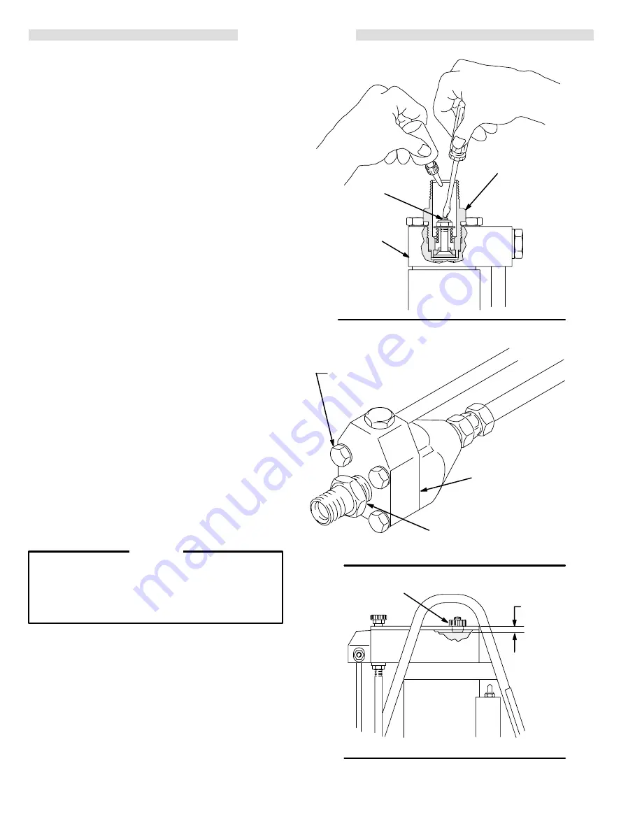
Lubricate the Inlet Valve (See Fig 9)
1.
Follow the Pressure Relief Procedure on page 11.
Remove the inlet screen.
2.
Turn the sprayer over. Press down lightly on the stem
of the inlet valve with a small screwdriver. Pour about
a teaspoon of mineral spirits or solvent into the valve,
then remove the screwdriver.
3.
Set the sprayer upright. Increase the pressure con-
trol setting half way. Turn on the sprayer for a few se-
conds, then turn it OFF.
4.
Now tighten the paint pump screws and the inlet
valve.
Tighten the Paint Pump Screws and Inlet Valve
(See Fig 10)
1.
Follow the Pressure Relief Procedure on page 11.
2.
Torque the four hex head screws on the paint pump
to 170–200 in–lb (19–23 N.m).
3.
Torque the inlet valve to 320–360 in–lb (36–41 N.m).
Check and/or Change the Hydraulic Oil (See Fig 11)
1.
Follow the Pressure Relief Procedure on page 11.
2.
Remove the fill cap. The oil should be 1 in. (25 mm)
from the top of the plate. If it is lower, add oil as nec-
essary. use only Graco lightweight hydraulic oil, part
no. 218–797. Reinstall the fill cap, hand tight, if you
are not going to change the oil.
3.
To change the oil, turn the sprayer over and drain the
oil through the fill cap hole.
Whenever you remove the fill cap, be very careful
not to let any dirt, paint particles, or other contami-
nants get into the hydraulic system. Contaminants
can cause serious damage to the hydraulic system.
CAUTION
4.
Fill the hydraulic pump housing with 16.5 ounces (55
ml) of Graco lightweight hydraulic oil. Reinstall the fill
cap.
5.
Plug in the sprayer. Turn the pressure control fully
counterclockwise (no pressure). Turn on the
sprayer and let it run for two minutes to fill the hydrau-
lic system. Increase the pressure to maximum and
turn the sprayer on and off four times to help rid the
hydraulic system of air.
Fig 9
Fig 10
Fig 11
STEM
PAINT PUMP
INLET VALVE
PUMP SHOWN UPSIDE DOWN
0272
0273
PAINT PUMP
TORQUE TO
320–360 in–lb
(36–41 N.m)
TORQUE TO
170–200 in–lb
(19–23 N.m)
0269
1”
(25 mm)
FILL CAP


