background image

4

307-711

SAFETY WARNINGS

HIGH PRESSURE SPRAY CAN CAUSE SERIOUS INJURY.

FOR PROFESSIONAL USE ONLY. OBSERVE ALL WARNINGS.

Read and understand all instruction manuals before operating the equipment.

FLUID INJECTION HAZARD

General Safety

This equipment generates very high fluid pressure. Spray from
the gun, leaks or ruptured components can inject fluid through
your skin and into your body, and cause extremely serious bodily
injury, including the need for amputation. Also, fluid injected or
splashed into the eyes or on the skin can cause serious damage.

NEVER point the spray gun at any one or at any part of the body.
NEVER put your hand or fingers over the spray tip. NEVER try
to “blow back” paint; this is NOT an air spray system.

ALWAYS have the tip guard in place on the spray gun when
spraying.

ALWAYS follow the PRESSURE RELIEF PROCEDURE,  below,
before cleaning or removing the spray tip or servicing any sys-
tem equipment.

NEVER try to stop or deflect leaks with your hand or body.

Be sure equipment safety devices are operating properly before
each use.

Medical Alert––Airless Spray Wounds

If any fluid appears to penetrate your skin, get EMERGENCY
MEDICAL CARE AT ONCE. DO NOT TREAT AS A SIMPLE
CUT
. Tell the doctor exactly what fluid was injected.

Note to Physician

Injection in the skin is a

 traumatic injury. It

is important to treat the injury surgically as soon as possible.
Do not delay treatment to research toxicity. Toxicity is a
concern with some exotic coatings injected directly into the
blood stream. Consultation with a plastic surgeon or reconstru-
ctive hand surgeon may be advisable.

Spray Gun Safety Devices

Be sure all gun safety devices are operating properly before
each use. Do not remove or modify any part of the gun; this can
cause a malfunction and result in serious bodily injury.
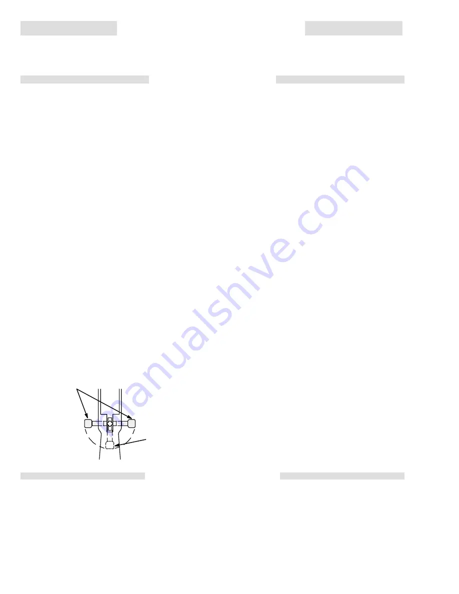
Safety Lever

Whenever you stop spraying, even for a moment, always set the
gun safety lever in the closed or “safe” position, making the gun
inoperative. Failure to set the safety lever can result in accidental
triggering. See the illustration below.

SAFETY LEVER IN
“OFF SAFE” OR
SPRAYING
POSITION

SAFETY LEVER IN

“ON SAFE” OR

INOPERATIVE

 POSITION

TRIGGER

View from front of gun

0268

Diffuser

The gun diffuser breaks up spray and reduces the risk of fluid in-
jection when the tip is not installed. Check diffuser operation
regularly. Follow the Pressure Relief Procedure, below, then
remove the spray tip. Aim the gun into a metal pail, holding the
gun firmly to the pail. Using the lowest possible pressure, trigger
the gun. If the fluid emitted 

is not diffused into an irregular stream,

replace the diffuser immediately.

Tip Guard

ALWAYS have the tip guard in place on the spray gun while
spraying. The tip guard alerts you to the fluid injection hazard
and helps reduce, but does not prevent, the risk of accidentally
placing your fingers or any part of your body close to the spray
tip.

Trigger Guard

Always have the trigger guard in place on the gun when spraying
to reduce the risk of accidentally triggering the gun if it is dropped
or bumped.

Spray Tip Safety

Use extreme caution when cleaning or changing spray tips. If the
spray tip clogs while spraying, engage the gun safety lever im-
mediately. ALWAYS follow the Pressure Relief Procedure, be-
low, and then remove the spray tip to clean it.

NEVER wipe off build–up around the spray tip until the pressure
is fully relieves and the gun safety is engaged.

Pressure Relief Procedure

To reduce the risk of serious bodily injury, including fluid injection,
splashing fluid or solvent in the eyes or on the skin, or injury from
moving parts or electric shock, always follow this procedure
whenever you shut off the sprayer, when checking or servicing
any part of the spray system, when installing, cleaning or chang-
ing spray tips, and whenever you stop spraying.

1. Shut off the sprayer and unplug it.

2. Hold a metal part of the gun firmly to the side of a grounded

metal pail, and trigger the gun into the paint pail to relieve
pressure.

3. Engage the gun safety lever.

4. Turn the bypass valve ONE turn counterclockwise to drain

paint back into the pail.

If you suspect that the spray tip or hose is completely clogged,
or that pressure has not been fully relieved after following the
steps above, very slowly loosen the part to relieve pressure
gradually, then loosen completely. Now clear the tip or hose.

EQUIPMENT MISUSE HAZARD

General Safety

Misuse of the spray equipment or accessories, such as over
pressurizing, modifying parts, using incompatible chemicals and
fluids, or using worn or damaged parts, can cause them to rup-
ture and result in fluid injection, splashing in the eyes or the skin,
or other serious injury, or fire, explosion or property damage.
NEVER alter or modify any part of this equipment; doing so could
cause it to malfunction.
CHECK all spray equipment regularly and repair or replace worn
or damaged parts immediately.
Always wear protective eyewear, gloves, clothing and respirator
as recommended by the fluid and solvent manufacturer.

System Pressure

This sprayer can develop 3000 psi (210 bar) 

MAXIMUM WORK

-

ING PRESSURE. Be sure all spray equipment and accessories
used are rated to withstand the this pressure. DO NOT exceed
the maximum working pressure of any component or accessory
used in the system.

Fluid and Solvent Compatibility

All chemicals used in the sprayer are chemically compatible with
the wetted parts shown in the TECHNICAL DATA on the back
cover. Always read the chemical manufacturer’s literature before
using them in this sprayer.

Summary of Contents for PT2500

Page 1: ...ing of gun by always setting safety latch when not spraying Never spray without a tip guard In case of accidental skin injection seek immediate Surgical Treatment Failure to follow this warning can result in amputation or serious injury FIRE AND EXPLOSION HAZARD SKIN INJECTION HAZARD READ AND UNDERSTAND ALL LABELS AND INSTRUCTION MANUALS BEFORE USE Spray painting flushing or cleaning equipment wit...

Page 2: ... could damage or destroy the equipment PRESSURE RELIEF PROCEDURE A safety proce dure for relieving fluid pressure in the system FLUID INJECTION INJURY A serious injury which may appear to be only a simple cut caused by the high pressure injection of fluid directly into the body NOTE Gives additional explanation of a procedure or helpful hints Hazard of Using Fluids Containing Halogenated Hydrocarb...

Page 3: ...lic fluid to operate the diaphragm Diaphragm The diaphragm separates the hydraulic and paint por tions of the paint pump Hydraulic oil causes the dia phragm to move up and down almost 30 times per sec ond no matter what pressure you are spraying at Pressure Control Knob The paint pressure is regulated by turning the pressure control knob clockwise to increase pressure and counterclockwise to decre...

Page 4: ...place on the spray gun while spraying The tip guard alerts you to the fluid injection hazard and helps reduce but does not prevent the risk of accidentally placing your fingers or any part of your body close to the spray tip Trigger Guard Always have the trigger guard in place on the gun when spraying to reduce the risk of accidentally triggering the gun if it is dropped or bumped Spray Tip Safety...

Page 5: ...on page 13 of this manual Follow the Pressure Relief Procedure on page 2 and remove the spray tip before flushing Hold a metal part of the gun firmly to the side of a grounded metal pail and use the lowest pos sible fluid pressure during flushing HOSE SAFETY High pressure fluid in the hoses can be very dangerous If the hose develops a leak split or rupture due to any kind of wear damage or misuse ...

Page 6: ...les risques d injection accidentelle quand l ajutage n est pas en place Véri fier le fonctionnement du diffuseur régulièrement Pour cette vé rification détendre la pression en observant la Marche à Suivre Pour Détendre la Pression donnée plus loin enlever l ajutage du pulvérisateur Pointer le pistolet dans un seau en métal en le maintenant fermement contre le seau puis en utilisant la pres sion la...

Page 7: ...ENDIE OU D EXPLOSION RISQUES D INCENDIE OU D EXPLOSION De l électricité statique est produite par le passage du fluide à grande vitesse dans la pompe et dans les tuyaux Si toutes les pièces de l appareil de pulvérisation ne sont pas convenable ment reliées ou à la masse ou à la terre des étincelles peuvent se produire et l appareil risques d être dangereux Des étincelles peuvent Également se produ...

Page 8: ... reduce el riesgo de inyección cuando no está instalada la boquilla Revi sar con regularidad el funcionamiento del difusor Seguir el pro cedimiento de descarga de presión dado más abajo y des pués sacar la boquilla Apuntar la pistola a un balde metálico sosteniéndola bien firme contra él Utilizando la presión más ba jo posible disparar la pistola Si el fluido emitido no sale disperso en un chorro ...

Page 9: ...perficie no conductiva como papel o cartón que interrumpe la continuidad a tierra 5 Objeto que se está rociando de conformidad con el código local 6 Todos los baldes de solvente usados durante el lavado de conformidad con el código local 7 Para mantener la continuidad a tierra durante el lavado o des carga de presión siempre apoyar una parte metálica de la pistola bien firme contra el costado de b...

Page 10: ...ary with lightweight hy draulic oil use only Graco Hydraulic Oil Part No 218 797 Install the fill cap See Fig 1 5 Check the electrical service It must be 120V 60 HzAc 15 Amp minimum Be sure the electrical out let is properly grounded You can use up to 100 ft 30 m of 3 wire 14 gauge minimum extension cord Longer extension cords may affect the sprayer performance Use more spray hose not longer exten...

Page 11: ...ar the tip or hose obstruction WARNING 1 Open the bypass valve ONE turn counterclock wise Do not place the pump intake in the pail yet See Fig 3 2 Turn the pressure control fully clockwise to increase pressure See Fig 3 3 Remove the inlet strainer and place your hand over the inlet valve to be sure it is drawing a vacuum NOTE If the inlet valve is not drawing a vacuum turn the sprayer OFF Turn the...

Page 12: ...ten the inlet valve and screws at the intervals indicated will result in oil leaking from the hydraulic system into the paint and can cause costly damage to the sprayer CAUTION Never start the electric motor with the inlet valve re moved as it will severely damage the diaphragm 11 If you have a Reverse A Clean IV tip guard on your gun and the tip clogs while spraying release the gun trigger engage...

Page 13: ...in the paint Now turn off the sprayer See Fig 7 2 Place the paint pump in a grounded flushing pail of solvent 3 Check to be sure the trigger safety lever is set Re move the spray tip from the gun Disengage the safe ty lever Hold a metal part of the gun firmly to the side of a grounded metal pail Close the bypass valve Trigger the gun into the pail Turn on the sprayer Watch the side of the pail for...

Page 14: ...hould be 1 in 25 mm from the top of the plate If it is lower add oil as nec essary use only Graco lightweight hydraulic oil part no 218 797 Reinstall the fill cap hand tight if you are not going to change the oil 3 To change the oil turn the sprayer over and drain the oil through the fill cap hole Whenever you remove the fill cap be very careful not to let any dirt paint particles or other contami...

Page 15: ... by increasing the fluid pressure Using the lowest pressure necessary to get the results you want will help prolong the life of your sprayer and minimize paint lost by overspray For interior corners such as on a bookcase or inside a cabinet aim the gun toward the center of the corner to spray By dividing the spray pattern this way the edges on both sides are sprayed evenly See Fig 14 Fig 14 0279 I...

Page 16: ...eplace gun Paint build up between needle and diffuser Disassemble and clean gun Spray gun leaks Worn seal or loose fluid fitting Repair gun order Kit no 218 588 tighten fluid fitting Spray gun won t spray or low output from gun Paint supply empty Refill and reprime system Spray tip clogged Use Reverse A Clean feature to clear tip clog see page 12 Gun filter if used is clogged Clean or replace Spra...

Page 17: ...nt pump Replace Sprayer sucks paint builds pres sure but presure drops when gun is No spray tip on gun Shut off sprayer and install tip sure but presure drops when gun is triggered Spray tip orifice too large for the paint or worn tip Try a smaller tip or a new tip Inlet screen clogged Clean Optional gun filter clogged Clean or replace Optional gun filter screen too fine for type of paint Install ...

Page 18: ... Fig 15 1 When removing the pressure control 4 to check or clean it always replace the seal 4a When replac ing the pressure control torque the new control 4 to 125 150 in lb 14 17 N m Starter Switch See Fig 15 1 Remove the cover of the switch box Remove the two screws holding the starter switch 18a Remove the old switch and install a new one Diaphragm See Fig 15 1 Remove the inlet strainer 27 Remo...

Page 19: ...8b 28a TORQUE TO 125 150 in lb 14 17 N m TORQUE TO 280 300 in lb 32 34 N m LUBRICATE AND TORQUE TO 170 200 in lb 19 23 N m C TORQUE TO 125 150 IN LB 14 17 N M 4 4a 38 37 36 APPLY THREAD SEALANT 66 35 3 67 APPLY THREAD SEALANT 20 LUBRICATE INTERNAL THREADS 28 18a Start Switch located in switch box 0284 DO NOT ALTER POSITION OF NUT ...

Page 20: ...LON TAPE TO TOP AND BOTTOM THREADS SEE DETAIL A PAGE 22 OUTLET APPLY THREAD SEALANT TO MOTOR TIE BOLTS APPLY SEALANT TO THREADS SEAL IN BEARING MUST FACE DOWN 41 39 61 62 37 36 LUBRICATE TORQUE TO 54 60 N m 40 45 in lb 33 TORQUE TO 15 16 N m 130 140 in lb DANGER LABEL ENGLISH DANGER LABEL FRENCH WARNING LABEL WARNING LABEL 17 92 97 95 40 57 58 101 102 0280 98 99 LABEL LABEL THIS SIDE LABEL FAR SID...

Page 21: ...O RING cylinder 1 42 183 840 CYLINDER pump 1 43 108 153 FITTING hose barbed 1 44 107 511 SPRING compression 1 45 180 479 PISTON 1 46 180 480 WASHER spring 1 47 107 517 RING retaining external 1 48 107 524 RING retaining external 1 49 107 513 KEY woodruff 1 50 218 909 ECCENTRIC ASSY 1 52 108 042 SCREW oval head cross head recessed M4 x 14 0 8 53 180 650 GASKET housing 1 54 107 518 BEARING ball 1 55...

Page 22: ...let check Includes replaceable item 26a 1 26a 180 446 GASKET 1 28 218 732 OUTLET CHECK VALVE ASSY Includes items 28a 28f 1 28a 180 455 SEAL washer 1 28b 218 968 HOUSING seat valve 1 28c 107 521 SPRING compression 1 28d 218 505 PLUG ball stop 28e 101 701 BALL carbide 1 28f 180 454 WASHER 1 10 12 11 15 Ref 17 DETAIL B BLACK WHITE GREEN 18a Located in this switch box 0282 20 21 22a 22b 26a 26 24 25 2...

Page 23: ...o free of charge Toll Free 1 800 328 0211 SERVICE INFORMATION Listed below by the assembly changed are Added and Deleted parts Added and deleted parts are not inter changable individually However to use the new drain valve on a Series A B or C sprayer order the new parts 187 952 235 198 and 224 771 and replace them together Assembly Changed Part Status Ref No Part No Name 218 796 To Series D Delet...

Page 24: ... the prepaid return of the equipment claimed to be defective to an authorized Graco distributor for verification of the claim If the claimed defect is verified Graco will repair or replace free of charge any defective parts The equipment will be returned to the original purchaser transportation prepaid If inspection of the equipment does not disclose any defect in material or workmanship repairs w...

Reviews: