background image

Warnings

312101E

3

Warnings

The following warnings are for the setup, use, grounding, maintenance, and repair of this 
equipment. The exclamation point symbol alerts you to a general warning and the hazard 
symbols refer to procedure-specific risks. Refer back to these warnings. Additional, product-
specific warnings may be found throughout the body of this manual where applicable.

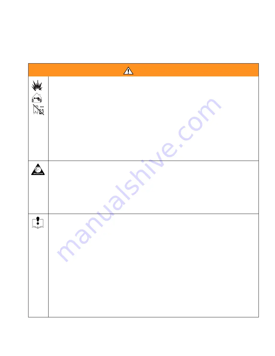
WARNING

FIRE AND EXPLOSION HAZARD 
Flammable fumes, such as solvent and paint fumes, in work area can ignite or explode. 
To help prevent fire and explosion:

Use equipment only in well ventilated area.

Eliminate all ignition sources; such as pilot lights, cigarettes, portable electric 
lamps, and plastic drop cloths (potential static arc). 

Keep work area free of debris, including solvent, rags and gasoline.

Do not plug or unplug power cords or turn lights on or off when flammable fumes 
are present.

Ground all equipment in the work area. See Grounding instructions.

If there is static sparking or you feel a shock, stop operation immediately. Do not 
use equipment until you identify and correct the problem.

Keep a working fire extinguisher in the work area.

PRESSURIZED EQUIPMENT HAZARD 
Fluid from the gun/dispense valve, leaks, or ruptured components can splash in the 
eyes or on skin and cause serious injury.

Follow Pressure Relief Procedure in this manual, when you stop spraying and 
before cleaning, checking, or servicing equipment. 

Tighten all fluid connections before operating the equipment.

Check hoses, tubes, and couplings daily. Replace worn or damaged parts 
immediately.

EQUIPMENT MISUSE HAZARD 
Misuse can cause death or serious injury.

Do not exceed the maximum working pressure or temperature rating of the lowest 
rated system component. See Technical Data in all equipment manuals.

Use fluids and solvents that are compatible with equipment wetted parts. See 
Technical Data in all equipment manuals. Read fluid and solvent manufacturer’s 
warnings.

Check equipment daily. Repair or replace worn or damaged parts immediately.

Do not alter or modify equipment.

Use equipment only for its intended purpose. Call your Graco distributor for 
information.

Route hoses and cables away from traffic areas, sharp edges, moving parts, and 
hot surfaces.

Do not kink or overbend hoses or use hoses to pull equipment.

Keep children and animals away from work area.

Comply with all applicable safety regulations.

Summary of Contents for RAZOR 288561

Page 1: ...arnings 3 Setup 4 Operation 4 Maintenance 5 Repair 6 Troubleshooting 7 Technical Data 8 Accessories 9 Parts 10 Graco Standard Warranty 12 Graco Information 12 Important Safety Instructions Read all warnings and instructions in this manual Save these instructions Includes LVLP HVLP Compliant and Conventional Series See page 2 for List of Models and maximum working pressures See page 10 for Parts En...

Page 2: ...1 253774 234779 289506 288575 A Compliant 35 0 24 2 4 1 0 Clear Base Primer 253825 253816 253769 288751 289502 288576 A Compliant 35 0 24 2 4 1 2 Clear Base Primer 253825 253817 253771 288752 289502 288577 A Compliant 35 0 24 2 4 1 3 Clear Base Primer 253825 253818 253771 288752 289502 288578 A Compliant 35 0 24 2 4 1 4 Clear Base Primer 253825 253819 253771 288752 289502 288657 A Compliant 35 0 2...

Page 3: ... working fire extinguisher in the work area PRESSURIZED EQUIPMENT HAZARD Fluid from the gun dispense valve leaks or ruptured components can splash in the eyes or on skin and cause serious injury Follow Pressure Relief Procedure in this manual when you stop spraying and before cleaning checking or servicing equipment Tighten all fluid connections before operating the equipment Check hoses tubes and...

Page 4: ...f toxic fumes burns and hearing loss This equipment includes but is not limited to Protective eyewear Clothing and respirator as recommended by the fluid and solvent manufacturer Gloves Hearing protection WARNING Check that your shop air provides adequate air flow Use a minimum 3 8 in 10 mm ID air hose Set shop air pressure regulator not supplied according to paint manu facturer s recommendation S...

Page 5: ...container until the equipment is clean 5 Relieve pressure page 4 Cleaning Gun and Cup 1 Flush page 5 2 Use a rag moistened in solvent to wipe outside of gun and cup 3 Make sure cup lid vent hole is clear 4 Blow dry gun inside and out Lubricate see Maintenance page 5 Cleaning Nozzle and Air Cap 1 Remove air cap 13 trigger gun remove nozzle 11 and soak both in a compatible cleaning solution 2 Clean ...

Page 6: ... Valve Replacement 1 Remove air control valve assembly 5 2 Insert replacement assembly 5 into gun Air Valve Replacement 1 Remove trigger nut 24 trigger pin 23 wave washer 18 and trigger 10 2 Remove knob 8 spring 29 needle 9 and nut 7 3 Remove spring 31 and push the air valve assembly 6 out the back of the gun 4 Inspect u cup seals 22 and replace if necessary 5 Lubricate gun as described in Mainte ...

Page 7: ...ir pressure and increase mate rial viscosity Correct pattern by narrowing fan size with spray width adjustment knob 8 Dirty or distorted air horn holes Clean and inspect air cap If pattern is not corrected replace air cap Gun spitting Air getting into paint stream Check if cup is empty and fill Tighten fluid nozzle 11 Check and tighten needle packing nut 17 Check fluid nozzle 11 for damage Will no...

Page 8: ... CFM at 35 psi 0 24 MPa 2 4 bar Conventional Gun 13 3 CFM at 43 psi 0 3 MPa 3 0 bar Fluid and Air Operating Temperature Range 32 F to 109 F 0 C to 43 C Spray Gun Air Inlet 1 4 npsm R1 4 19 Weight with cup 1 3 lbs 0 6 kg Sound Data LVLP sound pressure at 16 psi 0 1 MPa 1 1 bar 80 8 dB A LVLP sound power at 16 psi 0 1 MPa 1 1 bar 87 6 dB A HVLP sound pressure at 29 psi 0 2 MPa 2 0 bar 83 9 dB A HVLP...

Page 9: ...nlet Fitting Repair Kit 253934 Air Valve Repair Kit 289213 Cup gasket 10 Pack Kit Part No Description 288744 High Volume Air Adjusting Valve with Gauge 234387 High Output Precision Air Valve 288652 Digi tell Digital Air Adjusting Valve Part No Description 253975 PPS Adapter Part No Description 253447 LVLP Verification 253746 HVLP Primer 1 5 1 8 Verification 287985 HVLP Verification 287986 HVLP Pri...

Page 10: ...Insert u cup 16 with open end facing front of gun Apply lubricant Apply low strength thread retainer Apply thread sealant Torque to 85 90 in lbs 9 6 10 2 N m Torque to 15 20 in lbs 1 7 2 2 N m Torque to 175 185 in lbs 19 8 20 9 N m Torque to 155 165 in lbs 17 5 18 6 N m Install with valve assembly turned fully CCW to outermost position 1 2 3 4 5 6 7 8 9 10 9 5 10 6 8 3 4 6 10 9 1 3 3 3 2 3 2 8 7 3...

Page 11: ...53971 FITTING fluid inlet 1 5 253976 VALVE air control assy 1 6 VALVE air assy 1 7 NUT 1 8 KNOB fluid adjust 1 9 page 2 NEEDLE includes 9a 1 9a page 2 TIP needle 1 10 TRIGGER 1 11 page 2 NOZZLE includes 21 1 13 page 2 AIR CAP 1 14 253970 RING retaining 1 15 SPREADER needle packing 1 16 U CUP needle packing 1 17 253972 NUT needle packing 1 18 WASHER wave 1 19 O RING PTFE 1 20 WASHER UHMWPE 1 21 O R...

Page 12: ...or workmanship repairs will be made at a reasonable charge which charges may include the costs of parts labor and transportation THIS WARRANTY IS EXCLUSIVE AND IS IN LIEU OF ANY OTHER WARRANTIES EXPRESS OR IMPLIED INCLUDING BUT NOT LIMITED TO WARRANTY OF MERCHANTABILITY OR WARRANTY OF FITNESS FOR A PARTICULAR PURPOSE Graco s sole obligation and buyer s sole remedy for any breach of warranty shall ...

Reviews: