Repair
16
311512A
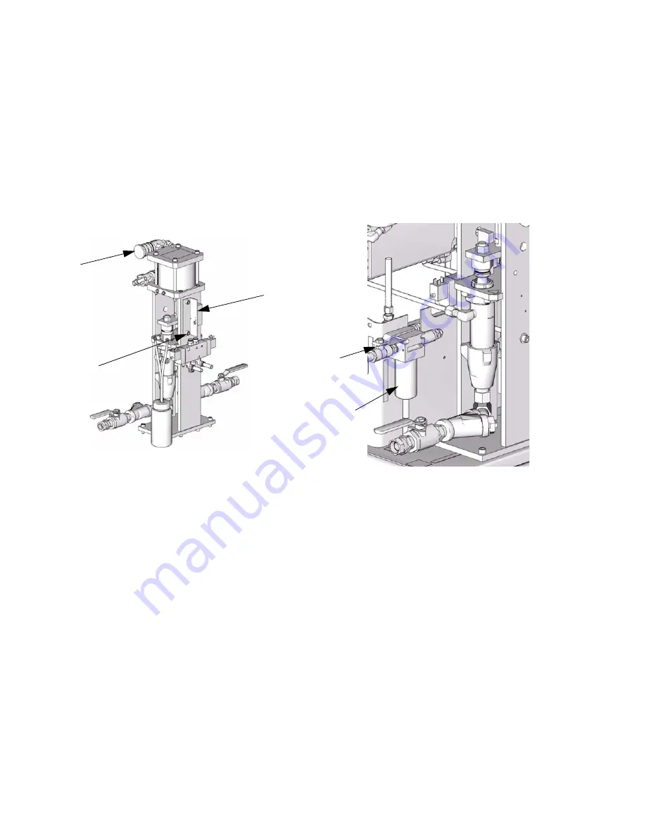
Reversing Switch
1.
Remove single screw and remove cover from
reversing switch (410).
2.
Inspect parts for damage or wear; replace switch
assembly if necessary.
3.
Disconnect wire from terminal block (follow wire
back to where it connects to terminal block and dis-
connect).
4.
Remove two screws (404) from mounting bracket.
Solenoid Valve Replacement
See A-20 Air Motor Pump Assembly, page 32.
1.
Disconnect all tubing attached to air control solenoid
valve (430). To disconnect, push end sleeve in and
pull tube. Mark each tube according to its corre-
sponding fitting.
2.
Loosen self-contained plug retaining screw on each
end and remove electronic plug.
3.
Remove three screws (424) on air control solenoid
valve.
4.
Replace fittings (425, 426, 428) and muffler (427)
onto new valve.
5.
Reattach mounting screws and plug retaining
screws.
6.
Reconnect all tubing lines.
Air Inlet Filter / Water Separator
(Auto Drain)
Air Filter Element Removal
See Air Inlet, page 30.
1.
Close air inlet valve (302) on filter (301).
2.
Hold in metal spring clip and twist black cover coun-
terclockwise to remove.
3.
Unscrew clear drain cover by hand.
4.
Unscrew black filter element retainer to remove ele-
ment.
5.
Inspect filter element. Clean or replace.
Air Filter Element Installation
1.
Insert cleaned or replacement filter (114228).
2.
Hand-screw filter retainer into place.
3.
Hand-screw clear drain cover until tight.
4.
Reposition black cover and turn. Make sure it
“snaps” back into place.
ti8487a
410
404
427
ti8456a
302
301
Summary of Contents for Reactor A-20
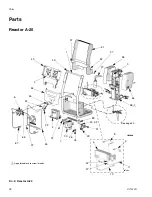
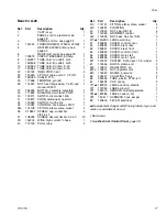
Page 31: ...Parts 311512A 31 ...
Page 35: ...Parts 311512A 35 ...
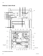
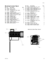
Page 38: ...Reactor A 20 Wiring Schematic 38 311512A Reactor A 20 Wiring Schematic ...
Page 39: ...Reactor A 20 Wiring Schematic 311512A 39 ...
Page 40: ...Reactor A 20 Wiring Schematic 40 311512A ...
Page 41: ...Reactor A 20 Wiring Schematic 311512A 41 ...
Page 42: ...Reactor A 20 Wiring Schematic 42 311512A ...
Page 43: ...Wiring Diagrams 311512A 43 Wiring Diagrams Heater Circuit ...
Page 44: ...Wiring Diagrams 44 311512A Pump Circuit ...
Page 45: ...Wiring Diagrams 311512A 45 Hose Circuit ...
Page 46: ...Wiring Diagrams 46 311512A ...


