


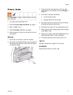

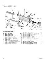

Replacing Control Components
22
311512A
Replacing Control Components
Hose Power Controller / Circuit
Breaker / Relays
Hose Heat Power Controller and Hose Transformer Sec-
ondary Circuit Breaker are DIN rail-mounted in the lower
cabinet. Unsnap them from the DIN replace them. See
Electrical Control Panel, page 28.
Hose Heat Power Controller
Place flat blade screwdriver under controller and pry
spring-loaded release tab above fan and against back
wall. Pivot bottom of unit towards front.
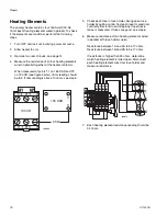
Circuit Breakers and Power Contactor
Relays
Pry tab on bottom down. Pivot bottom relays towards
front.
Digital Temperature Controller
1.
Carefully pry tabs away on back sides of case and
pull black connector off of controller.
2.
Squeeze in side tabs on black retainer clip.
3.
Pull clip off of controller.
4.
Push controller out towards front.
Rotating Panel Switches
1.
Push down thumb tab on back of switch assembly.
2.
Pull contact block assembly straight back.
3.
Use a small blade to unclip contact blocks and light
blocks.
4.
Unscrew round nut on back of knobs to remove.
Counter
1.
Pry tabs of retaining clip away from top and bottom
of counter body.
2.
Push counter out from back towards front.
Red Stop Switch
1.
Remove yellow locking tab on back of switch.
2.
Rotate metal tab counterclockwise.
3.
Pull contact block straight back and off.
4.
Unscrew round nut on back of knob to remove.
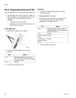
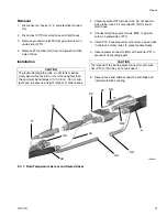
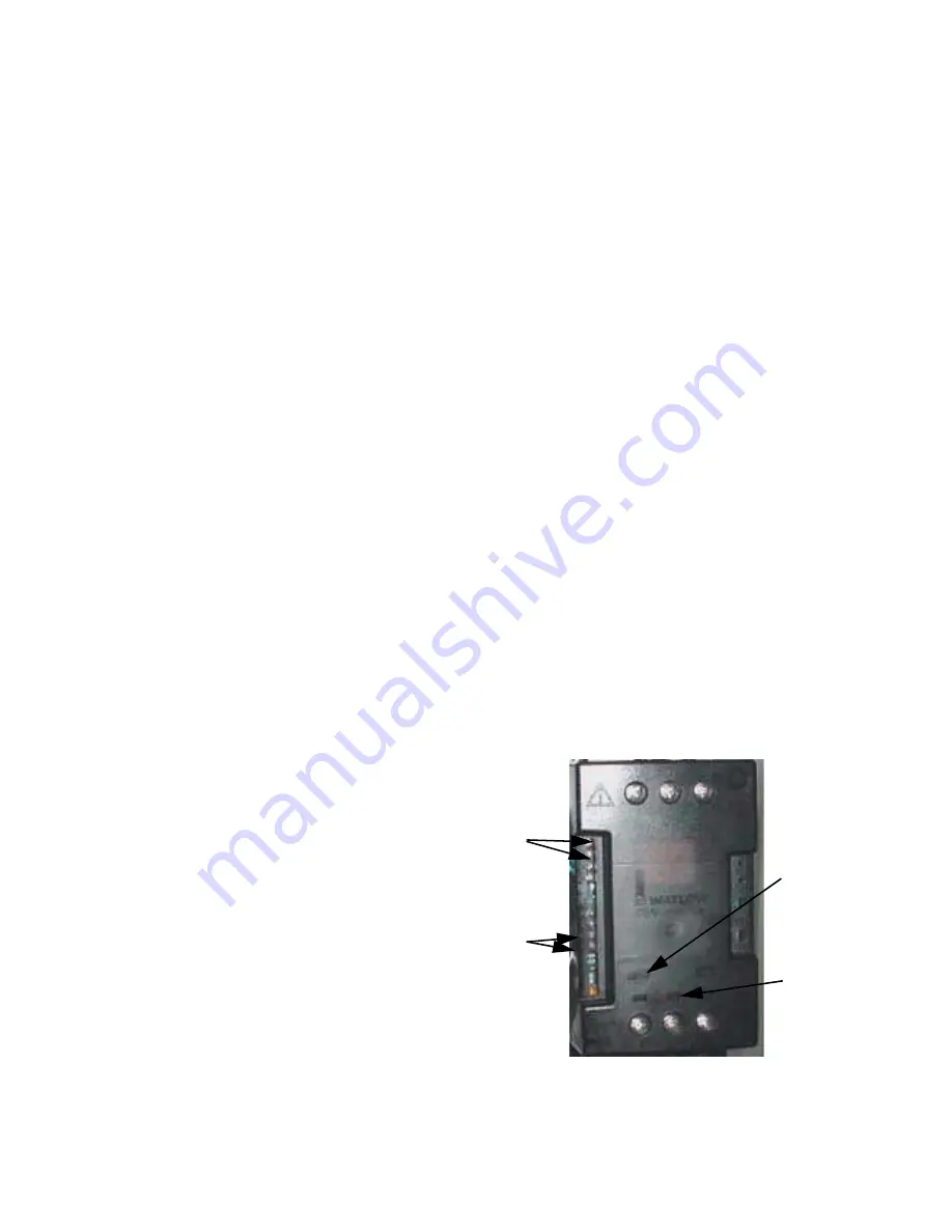
Checking Heated Hose Power Controller
The controller, next to the hose transformer in the lower
compartment, requires four conditions to be met for
proper function:
•
210 - 240 Vac to power the controller
•
4.5 - 5.5 Vdc to operate the control circuit
•
a complete electrical circuit through the hose heat-
ers, transformer secondary, and secondary circuit
breaker.
•
transformer secondary current sensor connected
with hose cable running through sensor doughnut.
If these four conditions are met, one green and one
orange status lights are illuminated. This only happens if
the hose temperature controller output light is on. If the
temperature controller light is flickering on less than
50%, the orange light may not be illuminated. No more
than 210 ft of hose on the machine.
Green
Signal
Light
Orange
Current
Limit
Light
4.5-5.5 VDC
Control
Signal
Current
Sensor
Connection
1
2
3
4
5
6
7+
8-
15
16
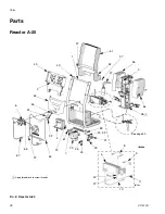
Summary of Contents for Reactor A-20
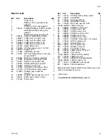
Page 31: ...Parts 311512A 31 ...
Page 35: ...Parts 311512A 35 ...
Page 38: ...Reactor A 20 Wiring Schematic 38 311512A Reactor A 20 Wiring Schematic ...
Page 39: ...Reactor A 20 Wiring Schematic 311512A 39 ...
Page 40: ...Reactor A 20 Wiring Schematic 40 311512A ...
Page 41: ...Reactor A 20 Wiring Schematic 311512A 41 ...
Page 42: ...Reactor A 20 Wiring Schematic 42 311512A ...
Page 43: ...Wiring Diagrams 311512A 43 Wiring Diagrams Heater Circuit ...
Page 44: ...Wiring Diagrams 44 311512A Pump Circuit ...
Page 45: ...Wiring Diagrams 311512A 45 Hose Circuit ...
Page 46: ...Wiring Diagrams 46 311512A ...


