Repair
311512A
15
Recirculation / Over Pressure
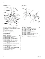
Relief Block
Valves can be serviced with the block on the machine
(see page 32 for parts view). For thorough cleaning,
remove the block assembly as follows.
1.
Remove both rear shrouds and lower front shroud;
see page 12.
2.
Disconnect two fluid tubes connected to back of
recirculation block.
3.
Loosen and remove two screws (ST) in back of
recirculation block.
4.
See Relief Manifold, page 30. Clean and inspect all
parts for damage. Ensure that the seat (8a) and
gasket (8b) are positioned inside each valve car-
tridge (8).
5.
Apply PTFE pipe sealant to all tapered pipe threads
before reassembling.
6.
Reassemble in reverse order, following all notes.
Air Motor
See A-20 Air Motor Pump Assembly on page 32.
1.
Remove four cover bolts (404) from outside hous-
ings (402). Leave fan connected.
2.
Raise retaining spring (444) and knock retaining
pins (436) out of pump rod slots. Leave yoke (415)
and link (414) in place.
3.
Press in tube fitting ferrules and pull out tubing to
disconnect air lines.
4.
Remove four bolts (408) to remove entire air motor
assembly.
5.
Remove lock nut (434) from piston rod (437) and
remove pump yoke (415).
6.
Remove four lock nuts (409), washers (407), and
tie-rod bolts (408).
7.
Lift top plate (406) and remove from air cylinder
(405).
8.
Push piston rod assembly out of the air cylinder and
replace piston o-ring (438) and lubricate.
9.
Replace bottom plate bearing (434), u-cup seal
(435), and lubricate. U-cup seal open end faces up.
10. Replace top and bottom o-rings (439) in the plates.
Use lubricant to hold in place.
11. Assemble in reverse order.
12. Torque tie rod bolts in small increments evenly to
17-22 in/lbs (3•4 Nm).
Air Motor Seal Repair Kit 255057 is available to
change all air motor seals.
ST
ti8485a
ti8491a
402
ti8457a
408
434
415
406
405
437
Summary of Contents for Reactor A-20
Page 31: ...Parts 311512A 31 ...
Page 35: ...Parts 311512A 35 ...
Page 38: ...Reactor A 20 Wiring Schematic 38 311512A Reactor A 20 Wiring Schematic ...
Page 39: ...Reactor A 20 Wiring Schematic 311512A 39 ...
Page 40: ...Reactor A 20 Wiring Schematic 40 311512A ...
Page 41: ...Reactor A 20 Wiring Schematic 311512A 41 ...
Page 42: ...Reactor A 20 Wiring Schematic 42 311512A ...
Page 43: ...Wiring Diagrams 311512A 43 Wiring Diagrams Heater Circuit ...
Page 44: ...Wiring Diagrams 44 311512A Pump Circuit ...
Page 45: ...Wiring Diagrams 311512A 45 Hose Circuit ...
Page 46: ...Wiring Diagrams 46 311512A ...


