Repair
18
311512A
Heating Elements
The primary heater contains four 1500-watt (30-36
ohms each) heating elements wired in parallel. To check
if the elements are functional, perform the following
steps:
1.
Turn OFF and lock out incoming power at source.
2.
Allow heater to cool.
3.
Remove two rear shrouds; see page 12.
4.
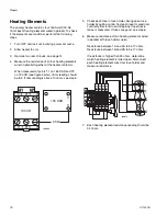
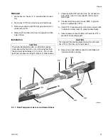
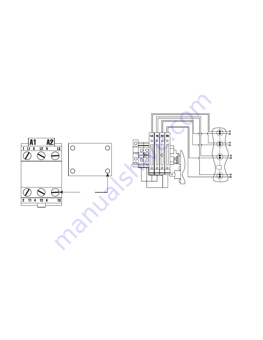
Measure the resistance of all four heating elements
wired in parallel together at the heater contactor.
When measured at points T1 on 165 SSR and T3
on 190 CR (see figure below), ohms reading should
be 8.5. If ohm reading is above 10 ohms, see step 5.
5.
Check each fuse in fuse holder. Swing open fuse
holder by pulling on tab. Test each fuse for electrical
continuity from end to end. Replace if open resis-
tance is measured. If fuses are good, see step 6.
6.
Measure resistance of two heating elements wired
in parallel with fuse holders open.
Resistance between 1A and 2A to be 17 ohms.
Resistance between 1B and 2B to be 17 ohms.
If resistance is higher than 25 ohms, determine
which heating element is failed open. Disconnect
each heating element wire from fuse holder and
measure resistance.
7.
Each heating element resistance reading should be
34 ohms.
,
4
&5
ȍ
665
ti8606a
ti8607a
Summary of Contents for Reactor A-20
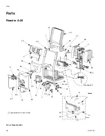
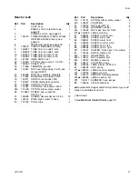
Page 31: ...Parts 311512A 31 ...
Page 35: ...Parts 311512A 35 ...
Page 38: ...Reactor A 20 Wiring Schematic 38 311512A Reactor A 20 Wiring Schematic ...
Page 39: ...Reactor A 20 Wiring Schematic 311512A 39 ...
Page 40: ...Reactor A 20 Wiring Schematic 40 311512A ...
Page 41: ...Reactor A 20 Wiring Schematic 311512A 41 ...
Page 42: ...Reactor A 20 Wiring Schematic 42 311512A ...
Page 43: ...Wiring Diagrams 311512A 43 Wiring Diagrams Heater Circuit ...
Page 44: ...Wiring Diagrams 44 311512A Pump Circuit ...
Page 45: ...Wiring Diagrams 311512A 45 Hose Circuit ...
Page 46: ...Wiring Diagrams 46 311512A ...


