Repair
311512A
19
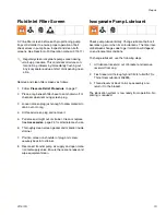
Fluid Inlet Filter Screen
A Y-line filter screen before each proportioning pump
traps solid matter to ensure proper operation of ball
check valves in pump base. Inspect and clean both
screens. See Reactor A-20 Operation manual (311511).
Remove and clean filter screens as follows:
1.
Follow Pressure Relief Procedure on page 7.
2.
Place a rag beneath filter base to catch drain-off of
chemical when removing screen plug.
3.
Loosen screen plug just enough to allow material to
drain out onto rag.
4.
Unthread screen plug and remove it.
5.
Pull screen straight out of strainer. Clean or replace.
See Accessories, page 24, for alternate mesh size.
6.
Thoroughly clean screen gasket and material inside
strainer.
7.
Position screen on shoulder of plug and screw
securely back into strainer.
8.
Reconnect transfer pump air supply and open mate-
rial inlet supply valve. Ensure there are no leaks and
wipe equipment clean.
Isocyanate Pump Lubricant
Check pump lubricant daily. Change lubricant before it
becomes a gel or when its color darkens. The time inter-
val between changes due to gel formation will depend
on environmental conditions.
To change lubricant, use the following steps.
1.
Lift lubricant reservoir out of bracket and remove
reservoir from cap.
2.
Flush reservoir thoroughly and fill 3/4 full with TSL
Throat Seal Lubricant 206995.
3.
Thread reservoir back onto cap assembly and
return it to the bracket.
The lubrication system is now ready from operation. No
priming is required.
Regularly clean isocyanate pump screen during
start-up procedure. This minimizes moisture con-
tamination problems by immediately flushing out
any isocyanate residue at start of dispensing oper-
ation.
Summary of Contents for Reactor A-20
Page 31: ...Parts 311512A 31 ...
Page 35: ...Parts 311512A 35 ...
Page 38: ...Reactor A 20 Wiring Schematic 38 311512A Reactor A 20 Wiring Schematic ...
Page 39: ...Reactor A 20 Wiring Schematic 311512A 39 ...
Page 40: ...Reactor A 20 Wiring Schematic 40 311512A ...
Page 41: ...Reactor A 20 Wiring Schematic 311512A 41 ...
Page 42: ...Reactor A 20 Wiring Schematic 42 311512A ...
Page 43: ...Wiring Diagrams 311512A 43 Wiring Diagrams Heater Circuit ...
Page 44: ...Wiring Diagrams 44 311512A Pump Circuit ...
Page 45: ...Wiring Diagrams 311512A 45 Hose Circuit ...
Page 46: ...Wiring Diagrams 46 311512A ...


