Repair
54
332144E
Electric Motor
Test Motor
If motor is not locked up by pumps, it can be tested
using a 9 V battery.
1.
Open recirculating valves.
2.
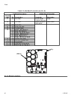
Disconnect motor connections from control board,
see F
. 12, page 46. Touch jumpers from battery to
motor connections. Motor should turn slowly and
smoothly.
Removal
NOTE: See wiring schematic, page 46.
1.
See Before Beginning Repair, page 40.
2.
Relieve pressure, page 24.
3.
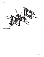
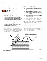
Remove four screws (91), shroud (89), and mount-
ing brackets (233). See F
IG
. 18.
4.
Remove fans (16) and disconnect cable (80). See
F
IG
. 20.
5.
Remove drive housing/pump assemblies, page 52.
6.
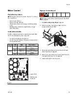
Remove display control cover (26). Disconnect
motor cables as follows:
a.
Unplug motor power connector before ferrite
(88).
b.
Unplug motor temp switch harness from con-
nector J9 and remove grounding cable from
grounding screw.
7.
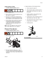
Remove RES supply tank. See Remove Supply
8.
Cut zip ties.
9. Thread motor power switch harness and over temp
switch out bottom of control module and cable chan-
nel, to free motor.
10. Remove screws (15) holding motor (201) to bracket.
Lift motor off unit.
11. If replacing motor, remove shroud mounting bolts
(207) and brackets (233) and set aside.
Installation
1.
If replacing motor, install fan assemblies (16) and
shroud mounting brackets (233) on new motor
(201).
2.
Place motor (201) and fans (16) on unit. Thread
motor switch harness through grommets in cart and
into the back of the display. See F
3.
Fasten motor (201) with screws (15) underneath.
Do not tighten yet.
4.
Plug motor temp switch harness to connector J9
and grounding cable from grounding screw.
5.
Plug in motor power connector.
6.
Secure all cables to cart frame with zip ties.
7.
Install display control cover (26).
8.
Install supply tank.
9.
Install drive housing/pump assemblies, page 52.
Reconnect inlet assemblies to pumps.
10. Torque screws (15) to 150 in.-lbs (17 N•m).
11. Return to service.
NOTICE
To prevent dropping the motor, two people may be
required to lift.

