background image

Repair

309813B

25

Heated Hose

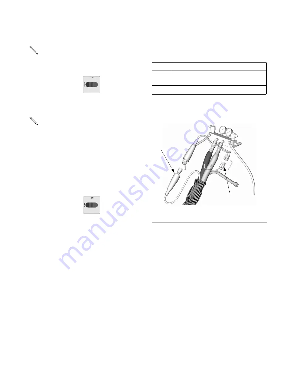
Check Hose Connectors

2.

Relieve pressure, page 11.

3.

Disconnect hose electrical connector (D) at Reac-
tor, F

IG

. 7.

4.

Using an ohmmeter, check between the two termi-
nals of hose connector (D). There should be conti-
nuity.

5.

If hose fails test, retest at each length of hose, 
including whip hose, until failure is isolated.

Check FTS Cables

2.

Relieve pressure, page 11.

3.

Disconnect FTS cable (F) at Reactor, F

IG

. 7.

4.

Test with ohmmeter between pins of cable connec-
tor. 

5.

If cable fails test, retest at FTS, page 26.

Refer to the heated hose manual 309572 for hose 
replacement parts.

1.

Turn main power OFF 

. Disconnect power 

supply.

Whip hose must be connected.

1.

Turn main power OFF 

. Disconnect power 

supply.

Pins

Result

1 to 2

approximately 35 ohms per 50 ft (15.2 m) of 
hose, plus approximately 10 ohms for FTS

1 to 3

infinity (

)

F

IG

. 7. Heated Hose

TI2726a

F

D

Summary of Contents for Reactor H-XP3 Elite

Page 1: ...right 2003 Graco Inc is registered to I S EN ISO 9001 309813B Repair Parts Air and Hydraulic Heated Plural Component Proportioners For spraying polyurethane foam and polyurea coatings Not for use in explosive atmospheres See Models on page 4 TI3699b Parts ...

Page 2: ...mocouple not connected 13 E05 Board overtemperature 13 Troubleshooting 14 Repair 17 Proportioning Pump 17 Circuit Breaker Module 18 Fan 19 Temperature Control Board 20 Heater 22 Heated Hose 25 Fluid Temperature Sensor FTS 26 Transformer 28 Display Module 32 Parts 35 Hydraulic Reactors Model H XP3 Shown 35 Hydraulic Reactors 36 Air Powered Reactors Model A XP2 Shown 38 Air Powered Reactors 39 Heat ...

Page 3: ...death if you do not follow instructions Symbols such as fluid injection shown alert you to a specific hazard and direct you to read the indicated hazard warnings on pages 8 9 CAUTION A caution alerts you to possible equipment damage or destruction if you do not follow instructions A note indicates additional helpful information ...

Page 4: ...liter Maximum Fluid Working Pressure psi MPa bar 246639 B A XP2 230V 1 62 14 540 10 200 1 3 8 0193 073 3000 20 7 207 246752 B A XP2 230V 3 40 14 540 10 200 1 3 8 0193 073 3000 20 7 207 246753 B A XP2 380V 3 22 14 540 10 200 1 3 8 0193 073 3000 20 7 207 Part No Series Model Voltage phase Full Load Peak Amps System Watts Heater Watts no hose Flow lb min kg min at 45 cpm Output per Cycle A B gal lite...

Page 5: ...ose Part No Series Model Voltage phase Full Load Peak Amps System Watts Heater Watts no hose 246365 B HT 6 0 230V 1 44 10 340 6 000 246760 B HT 6 0 230V 3 27 10 340 6 000 246761 B HT 6 0 380V 3 18 10 340 6 000 246607 B HT 10 2 230V 1 62 14 540 10 200 246762 B HT 10 2 230V 3 40 14 540 10 200 246763 B HT 10 2 380V 3 22 14 540 10 200 246364 B HT 15 3 230V 1 84 19 640 15 300 246764 B HT 15 3 230V 3 57...

Page 6: ...l English Motors one of following included Part No Description 306982 President Air Motor Models A 25 and A XP2 Repair Parts Manual English 309347 King Air Motor Model A 50 Repair Parts Manual English 307158 Viscount Hydraulic Motor Models H 50 and H XP3 Repair Parts Manual English Displacement Pumps one of following included Part No Description 307430 Displacement Pumps Models A 25 A XP2 and H XP...

Page 7: ...Parts Manual English Air Supply Kit Part No Description 309827 Instruction Parts Manual English for Feed Pump Air Supply Kit Circulation and Return Tube Kits Part No Description 309852 Instruction Parts Manual English Heated Hose Part No Description 309572 Instruction Parts Manual English Fusion Air Purge Spray Gun Part No Description 309550 Instruction Parts Manual English Fusion Mechanical Purge...

Page 8: ...RD Solvent and fumes in work area can ignite or explode High voltage components can cause electric shock To help prevent fire explosion and electric shock Shut off main power switch and wait 5 minutes before opening Reactor cabinet door All electrical wiring must be done by trained and qualified personnel and comply with all local codes Ground equipment and conductive objects See Grounding in the ...

Page 9: ... with all applicable safety regulations BURN HAZARD This equipment is used with heated fluid which can cause equipment surfaces to become very hot To avoid severe burns Do not touch hot fluid or equipment Allow equipment to cool completely before touching it Wear gloves if fluid temperature exceeds 110 F 43 C TOXIC FLUID OR FUMES HAZARD Toxic fluids or fumes can cause serious injury or death if sp...

Page 10: ...of fluid in system Do not use water WARNING Repairing this equipment requires access to parts which may cause electric shock or other serious injury if work is not performed properly Have a qualified electrician connect power and ground to main power switch terminals see the Operation manual Be sure to shut off all power to the equipment before repairing 1 Flush if necessary see right 2 Trigger gu...

Page 11: ...ower to motor 5 Turn PRESSURE RELIEF SPRAY valves SA SB to PRESSURE RELIEF Route fluid to waste con tainers or supply tanks Ensure gauges drop to 0 TI2421A SA SB TI3593a 6 Engage gun piston safety lock 7 Disconnect gun air line and remove gun fluid mani fold Pump throat seals work best under pressure Close fluid inlet valves VA VB when Reactor is depressurized to prevent drum head pressure from le...

Page 12: ...hose current with hose heater on Hose only 13 04 FTS or thermocouple not connected Individual 13 05 Board overtemperature All 13 For hose zone only if FTS is disconnected at startup display will show hose current 0A a Check connections between temperature control board and heater overtemperature switches page 24 b Check temperature sensors page 23 c Check temperature sensor is contacting heater el...

Page 13: ...t limiter continuity page 28 g Do Transformer Primary Check page 30 h Do Transformer Secondary Check page 30 a Check FTS operation by connecting directly to Reactor b Check cable connections between all hose lengths c Check temperature sensor connection at J1 on temperature control board page 20 d Check thermocouple with ohmmeter page 26 e Use manual current control mode see operation manual a Che...

Page 14: ...e See pump manual No display Main power OFF Turn main power ON Loose display cable Check cable connections page 32 Display board failed Check board replace page 32 No temperature display Loose display cable Check cable connections page 32 Failed temperature control board Open cabinet Check if board LED is blinking If not check power wiring connections to ensure board has power If board has power a...

Page 15: ...ker CB3 or CB4 page 18 Heat turned off Press or zone keys Temperature control alarm Check temperature displays for diag nostic code page 12 Defective heater Replace page 22 Check resistance Loose connectors or wire nuts Check connections Failed temperature control board Open cabinet Check if board LED is blinking If not check power wiring connections to ensure board has power If board has power an...

Page 16: ...ure board has power If board has power and LED is not blinking replace board page 20 Low hose heat A and B temperature setpoints too low Increase A and B setpoints Hose designed to maintain temperature not increase temperature Hose temperature setpoint too low Check Increase if necessary to maintain heat Flow too high Use smaller mix chamber Decrease pressure Low current FTS not installed Install ...

Page 17: ...urn main power OFF Disconnect power supply 6 Disconnect hoses and fittings from fluid inlets C and outlets D See FIG 1 A B SA SB TI3593a 7 Remove pump See applicable manuals supplied See page 6 for applicable pump and motor repair parts manuals Displacement pumps E may be removed without removing entire propor tioning pump 8 Reinstall in reverse order FIG 1 Pump Removal TI3582b C D C D E E ...

Page 18: ...ove bad breaker b Install new breaker and reconnect wires Depending on model 1 Turn main power OFF Disconnect power supply WARNING Read warnings page 8 Table 1 Circuit Breakers see FIG 2 Ref No Size Component 806 50 A Hose Transformer Secondary Side 817A 20 A Transformer Primary 804A 25 or 40 A Heater A 804B 25 or 40 A Heater B 817B 20 A Not Used FIG 2 Circuit Breaker Module TI2514A 804A 817B 806 ...

Page 19: ... 3 Replace if blown If good continue with step 4 4 Refer to electrical diagrams Disconnect fan wires from fuses F Thread wires through top of cabinet 5 Remove fan 6 Install fan in reverse order 1 Turn main power OFF Disconnect power supply WARNING Read warnings page 8 FIG 3 Fan Fuses F TI2514A 1 ...

Page 20: ...ure cycles D18 on Zone B turned on D19 cycles on and off Zone B powered LED cycles as temperature cycles D27 on Hose zone turned on D15 cycles on and off Hose zone powered LED cycles as temperature cycles CAUTION Before handling board put on a static conductive wrist strap to protect against static discharge which can damage board Follow instructions provided with wrist strap 1 Turn main power OFF...

Page 21: ...Repair 309813B 21 FIG 4 Temperature Control Board 1 Apply 110009 thermal heatsink compound to mating surfaces 1 TI2572a J1 J5 J13 J9 J2 J8 D15 D27 D19 D26 D18 D13 D14 B A ...

Page 22: ... temperature sensor 211 to avoid damage 6 Remove heater element 207 from tube 201 Be careful not to spill any fluid left in tube 7 Install new heater element 207 holding mixer 202 so it does not interfere with sensor port P 8 Reinstall temperature sensor page 23 9 Reconnect wires and secure with connector 63 and electrical tape 1 Turn main power OFF Disconnect power supply WARNING Read warnings pa...

Page 23: ...1 to a mini mum depth of 0 81 in 20 6 mm If minimum is not achieved mixer must be moved before pro ceeding c Apply PTFE tape and thread sealant to male threads and tighten sensor housing H into tube 201 d Push in sensor 211 so tip T contacts heater element 207 avoiding mixer 202 e Tighten ferrule nut N holding sensor T against heater element 9 Route wires into cabinet and thread into bundle as bef...

Page 24: ... approximately 0 ohms 5 If switch fails test cut off clamps with wire clippers Remove switch Install new switch in same location on tube 201 and secure with hose clamps 203 Reconnect wires 1 Turn main power OFF Disconnect power supply WARNING Read warnings page 9 Wait for heaters to cool before repairing If wires need replacement disconnect from tem perature control board See TABLE 3 page 20 and F...

Page 25: ...s isolated Check FTS Cables 2 Relieve pressure page 11 3 Disconnect FTS cable F at Reactor FIG 7 4 Test with ohmmeter between pins of cable connec tor 5 If cable fails test retest at FTS page 26 Refer to the heated hose manual 309572 for hose replacement parts 1 Turn main power OFF Disconnect power supply Whip hose must be connected 1 Turn main power OFF Disconnect power supply Pins Result 1 to 2 ...

Page 26: ...obe H Do not bend or kink probe Insert in component A ISO side of main hose 2 Connect whip hose ground wire K to ground screw on underside of FTS 3 Install FTS in reverse order of removal Leave slack G in cables as stress relief to prevent cable failure 4 Secure hose and cable connections with tape and install protective covering 1 Turn main power OFF Disconnect power supply Pins Result 1 to 2 app...

Page 27: ...Repair 309813B 27 FIG 8 Fluid Temperature Sensor and Heated Hoses 11 TI2684a1 B A A B K H C D L D F T G W ISO ...

Page 28: ... on 20A hose circuit breaker 817A d Connector pin 4 P4 and PA on transformer ter minal block B e Connector pin 5 P5 and T3 on 50A hose circuit breaker 806 Test Current Sensor Continuity 2 Disconnect 14 pin connector from J1 on tempera ture control board page 20 3 Using an ohmmeter test for continuity across pins 5 and 6 of connector not board Reading should be 20 25 ohms If not replace current sen...

Page 29: ...tinuity Tests TI3470b C B R TI3934a TI4335A 806 817A P P1 T1 PB T2 PA T3 L 32 Detail A Terminal Block Detail B Circuit Breaker Module and Hose Heat Wire Harness P2 P3 P4 P5 P6 J13 on Temperature Control Board PC To J1 Connector pins 5 and 6 ...

Page 30: ...empera ture control board page 20 1 Ensure that all harnesses cables and connectors are properly connected Connect hose 2 Connect power supply Turn main power ON 3 Set hose heat target temperature below current hose temperature 4 Turn on heat zone by pressing WARNING Read warnings page 8 Step 5 measures line voltage and should be done by a qualified electrician If work is not performed properly it...

Page 31: ...t 6 Install new transformer in reverse order Use this procedure to replace transformer To replace terminal block B and wire harness C only order Part No 248113 Transformer Repair Kit See manual 309930 1 Turn main power OFF Disconnect power supply WARNING Read warnings page 8 Wait 5 min for stored voltage to discharge E 30 and E XP2 models only FIG 10 Transformer TI3470b C T4 B R TI3934a TI2514A 80...

Page 32: ... FIG 11 11 Replace board 401 or 402a or membrane switch 402b as necessary 12 Reassemble in reverse order see FIG 11 Apply medium strength thread sealant where shown Be sure display cable ground wire G is secured between cable bushing and cover 404 with screws 412 FIG 11 Also check ground connection at rear of Reactor see below CAUTION Before handling board put on a static conductive wrist strap to...

Page 33: ...e TI3703a 402 401 403 404 405 J1 407 408 409 410 J13 412 406 411 TI3702a 120 401 402b 402c 402a G J1 J13 R Detail of Membrane Switches and Display Boards Temperature Display Cycle Counter Display Apply medium strength thread sealant 1 1 1 1 ...

Page 34: ...play 401 and cycle counter display 402 7 Remove red stop button 406 8 Reassemble in reverse order Be sure display cable ground wire G is secured between cable bushing and cover 404 with screws 412 CAUTION Before handling board put on a static conductive wrist strap to protect against static discharge which can damage board Follow instructions provided with wrist strap 1 Turn main power OFF Disconn...

Page 35: ... 37 28 29 44 30 38 18 26 Detail of Cycle Counter Switch Ref No 23 used on H 50 Models only Not shown in this view 1 1 Ref No 26 Magnet is on back side of yoke 2 2 20 Dimension from bottom of switch mounting plate 18 to top of tie plate must be 2 in 51 mm to maintain correct relationship between magnet 26 and switch 27 3 3 42 23 45 43 ...

Page 36: ...100490 4 SCREW cap hex hd 3 8 16 x 1 1 2 in 38 mm 100003 100003 100003 4 8 WASHER lock 3 8 in 100133 100133 100133 100133 100133 100133 4 9 NUT hex 3 8 16 100131 100131 100131 100131 100131 100131 4 10 ELBOW swivel 1 in npt m x 1 in npt f 118461 118461 118461 2 ELBOW swivel 3 4 npt m x 3 4 npt f 118462 118462 118462 2 11 Y STRAINER includes 11a 110878 110878 110878 101078 101078 101078 2 11a ELEME...

Page 37: ...in 22 mm 107438 107438 107438 2 31 HOSE fluid nylon 1 2 npsm fbe 1 2 in 13 mm ID 5 ft 1 52 m 240632 240632 240632 2 HOSE fluid nylon 3 8 npt mbe 3 8 in 10 mm ID 5 ft 1 52 m 215247 215247 215247 2 36 OIL ISO pump not shown 217374 217374 217374 217374 217374 217374 1 37 CONNECTOR 5 pin 24 AWG 118115 118115 118115 118115 118115 118115 1 38 BRACKET mounting switch 15C319 15C319 15C319 15C319 15C319 15...

Page 38: ...4 38 18 26 Detail of Cycle Counter Switch Ref No 26 Magnet is on back side of yoke 2 2 16 10 12 13 11 14 Ref No 25 used on A 50 Models only Not shown in this view 1 1 17 Dimension from bottom of switch mounting plate 18 to top of tie plate must be 2 in 51 mm to maintain correct relationship between magnet 26 and switch 27 3 3 ...

Page 39: ...8 100468 4 8 WASHER lock 3 8 in 100133 100133 100133 100133 100133 100133 100133 100133 100133 4 9 NUT hex 3 8 16 100131 100131 100131 100131 100131 100131 100131 100131 100131 4 10 ELBOW swivel 3 4 npt m x 3 4 npt f 118462 118462 118462 118462 118462 118462 2 ELBOW swivel 1 in npt m x 1 in npsm f 118461 118461 118461 2 11 Y STRAINER includes 11a 101078 101078 101078 110878 110878 110878 101078 10...

Page 40: ... 110982 110982 110982 4 30 SCREW machine 5 40 x 7 8 in 22 mm 107438 107438 107438 107438 107438 107438 2 SCREW machine 5 40 x 1 2 in 13 mm 100974 100974 100974 2 31 HOSE fluid nylon 3 8 npt mbe 3 8 in 10 mm ID 5 ft 1 52 m 215247 215247 215247 215247 215247 215247 2 HOSE fluid nylon 1 2 npsm fbe 3 8 in 10 mm ID 5 ft 1 52 m 240632 240632 240632 2 36 OIL ISO pump not shown 217374 217374 217374 217374...

Page 41: ...rts 309813B 41 Heat Control Package TI3707a 119 TI3708b 153 192 104 159 158 140 117 103 190 191 138 107 112 141 110 187 137 186 189 109 124 125 101 120 106 116 170 196 197 172 102 114 113 126 135 122 148 ...

Page 42: ...Parts 42 309813B TI2606A 133 194 131 160 108 141 123 130 105 128 161 162 129 142 TI3705a 134 127 ...

Page 43: ...NSFORMER see page 55 15B352 15B352 15B352 15B352 15B352 15B352 15B352 15B352 15B352 1 109 COVER wire access 15B775 15B775 15B775 15B775 15B775 15B775 15B775 15B775 15B775 1 110 DOOR cabinet 246976 246976 246976 246976 246976 246976 246976 246976 246976 1 111 SENSOR fluid temperature 246079 246079 246079 246079 246079 246079 246079 246079 246079 1 112 GASKET manifold 15B456 15B456 15B456 15B456 15B...

Page 44: ...4 117564 117564 117564 1 134 SWITCH main power 117545 117545 117545 117545 117545 117545 117545 117545 117545 1 135 SCREW machine 6 32 x 2 in 51 mm 117723 117723 117723 117723 117723 117723 117723 117723 117723 4 137 WIRE hose 15B396 15B396 15B396 15B396 15B396 15B396 15B396 15B396 15B396 1 138 TUBE 1 4 in 6 mm ID 3 8 in 16 mm OD 2 ft 1 2 m PTFE buy locally buy locally buy locally buy locally buy ...

Page 45: ...4 100016 100016 100016 100016 100016 100016 100016 100016 100016 15 184 WASHER plain 3 16 100086 100086 100086 100086 100086 100086 100086 100086 100086 8 186 REDUCER 5 x 8 JIC 117502 117502 117502 117502 117502 117502 117502 117502 117502 1 187 REDUCER 6 x 10 JIC 117677 117677 117677 117677 117677 117677 117677 117677 117677 1 189 COUPLING hose 1 4 npsm f 205447 205447 205447 205447 205447 205447...

Page 46: ... 117532 ELBOW 1 2 npt x 1 2 in 13 mm OD tube 2 214 248187 RUPTURE DISK KIT see 309969 1 201 203 208 202 211 206 213 205 207 210 TI2512b 211 Ref No 182 not included with heater Order separately see page 45 214 182 Ref No Part No Description Qty 201 15B134 HOUSING 2 202 15B135 MIXER 3 203 118426 CLAMP 6 204 15B133 CROSSOVER 2 205 15B132 MANIFOLD 2 206 107218 SCREW 8 207 15B138 HEATER immersion 2550 ...

Page 47: ...ly see page 45 214 Ref No Part No Description Qty 201 15B134 HOUSING 2 202 15B135 MIXER 4 203 118426 CLAMP 8 205 15B132 MANIFOLD 4 206 107218 SCREW 8 207 15B140 HEATER immersion 1500 W 230v 4 208 15B137 SWITCH overtemperature 4 210 100361 PLUG 2 211 117484 SENSOR temperature 2 213 117532 ELBOW 1 2 npt x 1 2 in 13 mm OD tube 4 214 248187 RUPTURE DISK KIT see 309969 2 ...

Page 48: ...mperature includes 402a 402c 1 402a 246130 BOARD circuit 1 402b 246479 SWITCH membrane 1 402c 112324 SCREW 4 403 15B293 GASKET 1 404 15B292 COVER 1 405 15B291 PLATE 1 406 246287 HARNESS wire red stop button 1 407 117499 HANDLE 2 408 117523 NUT cap 10 24 8 409 111008 SCREW tapping 6 32 1 4 in 6 mm 8 410 111393 SCREW machine pan hd M5 x 0 8 16 mm 4 411 15B386 CABLE display 1 412 195853 SCREW machine...

Page 49: ... 502 503 504 505 1 Apply 110009 thermal heatsink compound to mating surfaces 1 Ref No Part No Description Qty 501 15B779 HEAT SINK 1 502 246194 BOARD temperature control 1 503 117683 SCREW 6 32 x 1 1 2 in 38 mm 2 504 117526 SPACER 5 505 104590 SCREW machine 6 32 x 3 8 in 10 mm 5 ...

Page 50: ...ndles facing away from each other 6 6 6 3 3 3 3 Ref No Part No Description Qty 701 15B332 MANIFOLD aluminum 1 702 246161 VALVE pressure relief spray 2 704 102814 GAUGE 5000 psi 35 MPa 350 bar 2 705 162453 NIPPLE 1 4 npt x 1 4 npsm 2 706 198241 PLUG pressure 11 16 24 unef 2 707 193709 SEAT valve carbide 2 708 193710 SEAL seat nylon 2 709 15B287 HANDLE valve 2 710 114708 SPRING 2 711 117623 NUT cap ...

Page 51: ...agrams supplied See page 54 for parts list Part No 246087 A 25 A XP2 Part No 246089 A 50 816 811 813 817 808 801 804 810 817 806 815 809 802 819 803 814 818 L1 L2 L3 GND To Hose To Hose Transformer To Temperature Control Board J2 A To Temperature Control Board J13 Hose To Temperature Control Board J14 To Temperature Control Board J9 B ...

Page 52: ...lied See page 54 for parts list Part No 246090 A 25 A XP2 Part No 246092 A 50 816 811 813 817 808 801 804 810 817 806 815 809 802 819 803 814 818 L1 L2 GND To Hose To Hose Transformer To Temperature Control Board J2 A To Temperature Control Board J13 Hose To Temperature Control Board J14 To Temperature Control Board J9 B ...

Page 53: ...4 for parts list 816 811 813 817 808 801 804 Part No 246096 A 25 A XP2 Part No 246098 A 50 810 817 806 815 809 802 819 803 814 818 To Hose To Hose Transformer To Temperature Control Board J2 A To Temperature Control Board J13 Hose To Temperature Control Board J14 To Temperature Control Board J9 B B Heaters A Heaters L1 L2 L3 Neutral GND ...

Page 54: ...9 117679 3 CONNECTOR power lug 117679 117679 2 808 CABLE harness 230V 3 phase 15B387 15B387 1 CABLE harness 230V 1 phase 117674 117674 1 CABLE harness 380V 3 phase 15B377 15B377 1 809 TERMINAL block 117796 117796 117796 117796 117796 117796 2 810 CABLE harness power temp 15B375 15B375 15B375 15B375 15B375 15B375 1 811 CABLE hose heat 15B378 15B378 15B378 15B378 15B378 15B378 1 813 BLOCK terminal g...

Page 55: ...Parts 309813B 55 Transformer Part No 15B352 Transformer To replace terminal block B and wire harness H only order Part No 248113 Transformer Repair Kit See manual 309930 TI3470a C T B H ...

Page 56: ...del A 50 3 4 npsm f Recommended Air Supply Hose Size Models A 25 and A XP2 1 2 in 13 mm ID minimum Model A 50 3 4 in 19 mm ID minimum Air Consumption Model A 25 40 scfm at 120 psi 0 82 MPa 8 2 bar 1 6 gpm 6 1 lpm Model A XP2 40 scfm at 120 psi 0 82 MPa 8 2 bar 1 0 gpm 3 8 lpm Model A 50 80 scfm at 75 psi 0 5 MPa 5 bar 5 0 gpm 19 lpm 35 scfm at 75 psi 0 5 MPa 5 bar 2 0 gpm 7 6 lpm Hydraulic Supply ...

Page 57: ...4 Heater Power A and B heaters no hose Model HT 6 0 6000 Watts Models A 25 A XP2 and HT 10 2 10200 Watts Models A 50 H 50 H XP3 and HT 15 3 15300 Watts Sound Power per ISO 9614 2 Model A 25 94 7 dB A at 1000 psi 7 MPa 70 bar 3 0 gpm 11 4 lpm 15 cpm Model A 50 86 5 dB A at 1000 psi 7 MPa 70 bar 3 0 gpm 11 4 lpm 15 cpm Model A XP2 94 7 dB A at 2000 psi 14 MPa 140 bar 0 5 gpm 1 9 lpm 15 cpm Model H 5...

Page 58: ...epairs will be made at a reasonable charge which charges may include the costs of parts labor and transportation THIS WARRANTY IS EXCLUSIVE AND IS IN LIEU OF ANY OTHER WARRANTIES EXPRESS OR IMPLIED INCLUDING BUT NOT LIMITED TO WARRANTY OF MERCHANTABILITY OR WARRANTY OF FITNESS FOR A PARTICULAR PURPOSE Graco s sole obligation and buyer s sole remedy for any breach of warranty shall be as set forth ...

Reviews: