
Repair
20
312408F
Test SCR Circuit
1.
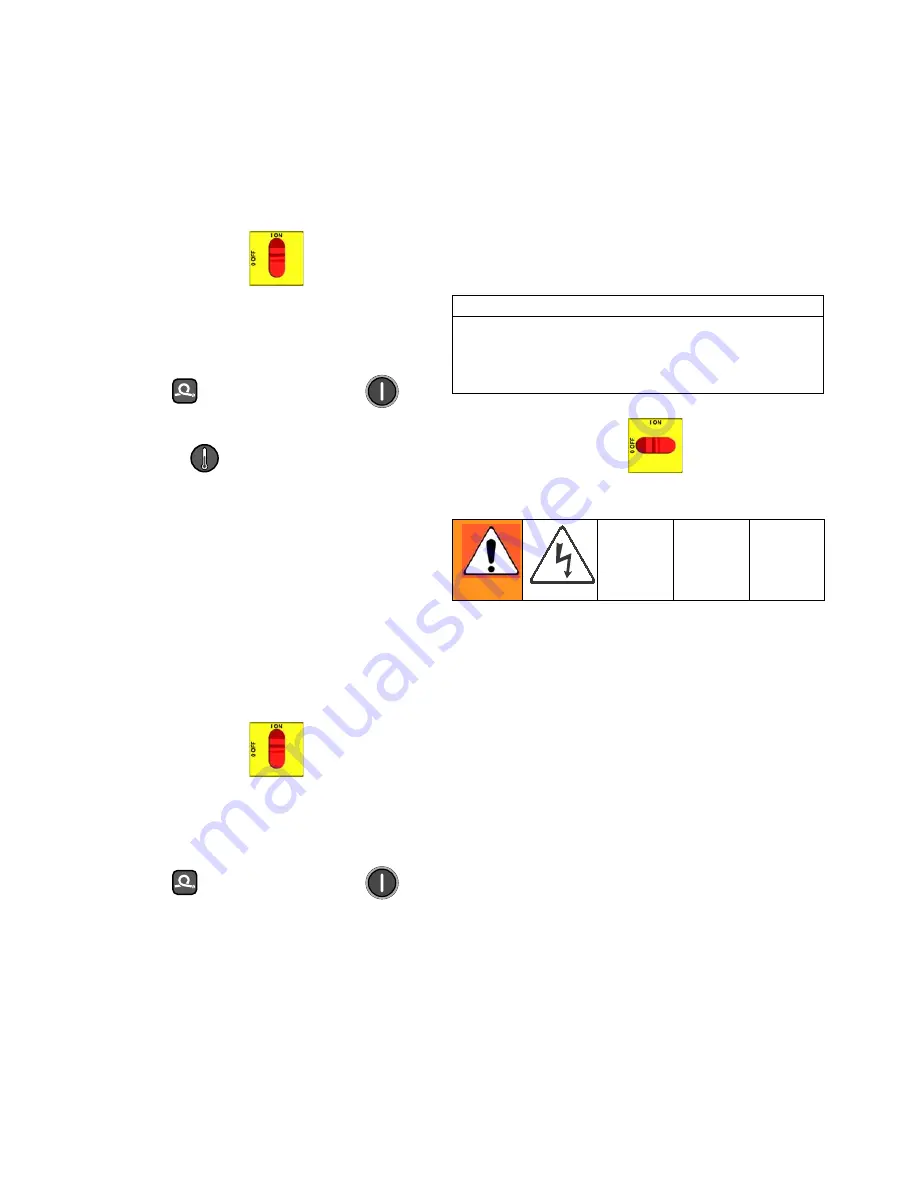
Test the SCR circuit in the on position:
a.
Make sure everything is connected, including
the hose.
b.
Turn main power ON
.
c.
Adjust the hose heat setpoint above the ambi-
ent hose temperature.
d.
Turn on
heat zone by pressing
.
e.
Hold down
to view electrical current.
Hose current should ramp up to 45A. If there is
no hose current, see E03: No zone current,
page 8. If hose current exceeds 45A, see E02:
High zone current, page 8. If hose current
stays several amps below 45A, hose is too long
or voltage is too low.
2.
Test the SCR circuit in the off position:
a.
Make sure everything is connected, including
the hose.
b.
Turn main power ON
.
c.
Adjust the hose heat setpoint below the ambi-
ent hose temperature.
d.
Turn on
heat zone by pressing
.
e.
Using a voltmeter, carefully measure the voltage
at the hose connector. You should not get a volt-
age reading. If you do, the SCR on the tempera-
ture control board is bad. Replace the
temperature control assembly.
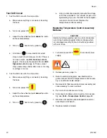
Replacing Temperature Control Assembly
Modules
1.
Turn main power OFF
. Disconnect power
supply.
2.
Relieve pressure, page 15.
3.
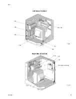
Refer to electrical diagrams; see Electrical Dia-
grams manual 312409. Temperature control assem-
bly is on left side inside cabinet.
4.
Remove bolts that secure transformer assembly and
slide assembly to side in cabinet.
5.
Put on static conductive wrist strap.
6.
Disconnect all cables and connectors from assem-
bly; see Parts - Temperature Control, page 38.
7.
Remove nuts and take entire temperature control
assembly to workbench.
8.
Replace defective module.
CAUTION
Before handling assembly, put on a static conductive
wrist strap to protect against static discharge which
can damage assembly. Follow instructions provided
with wrist strap.
Summary of Contents for Reactor HT Series
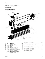
Page 43: ...Parts 312408F 43 ...


