


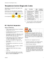

Temperature Control Diagnostic Codes
8
312408F
4.
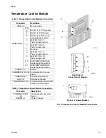
Remove connector B from temperature control mod-
ule, and check continuity of overtemperature
switches A and B, thermocouples A and B, or FTS
by measuring resistance across the pins on the plug
end; see T
ABLE
1.
5.
Verify fluid temperature, using an external tempera-
ture sensing device.
•
If temperature is too high (sensor reading is
229°F [109°C] or above):
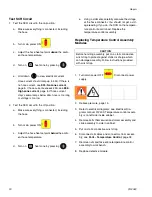
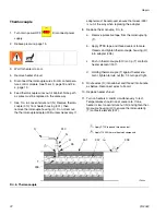
6.
Check if thermocouples A and B are damaged, or
not contacting the heater element, page 22.
7.
To test that temperature control module turns off
when equipment reaches temperature setpoint:
a.
Set temperature setpoints far below displayed
temperature.
b.
Turn zone on. If temperature rises steadily,
power board is failing.
c.
Verify by swapping with another power module.
See Replacing Temperature Control Assem-
bly Modules, page 20.
d.
If the swapped module does not fix the problem,
the power module is not the cause.
8.
Verify continuity of heater elements with an ohmme-
ter, see page 21.
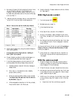
E02: High zone current
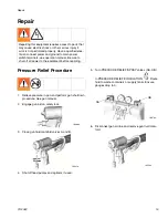
1.
Turn main power OFF
.
2.
Relieve pressure, page 15.
3.
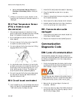
Disconnect hose connector (D) at Reactor.
4.
Using an ohmmeter, check between the two termi-
nals of the connector (D). There should be no conti-
nuity.
5.
Exchange zone module with another one. Turn zone
on and check for error. If error disappears, replace
faulty module.
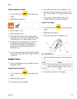
For hose zone: If error still occurs, perform Transformer
Primary Check and Transformer Secondary Check
starting on page 25.
E03: No zone current
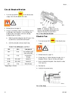
1.
Check for tripped circuit breaker inside electrical
cabinet or at power source for that zone. Replace
circuit breaker if it trips habitually.
2.
Check for loose or broken connection at that zone.
3.
Exchange zone module with another one. Turn zone
on and check for error (see page 20). If error disap-
pears, replace faulty module.
4.
If E03 occurs for all zones, the contactor may not be
closing. Verify wiring from heater control to contac-
tor coil.
a.
Hose zone: test hose continuity, page 23.
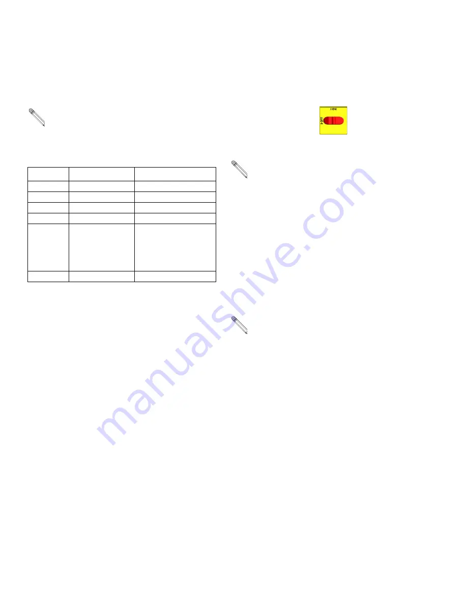
Before doing the following checks, note which zone
(A, B, FTS, or all) has high fluid temperature.
Table 1: Sensor Connector Continuity Checks
Pins Description
Reading
1 & 2
OT switch A
nearly 0 ohms
3 & 4
OT switch B
nearly 0 ohms
5 & 6
Thermocouple A
4-6 ohms
8 & 9
Thermocouple B
4-6 ohms
11 & 12
FTS
approximately 35
ohms per 50 ft (15.2
m) of hose, plus
approximately 10
ohms for FTS
10 & 12
FTS
open
Disconnect whip hose.
When there is a a high current error, the LED on
that zone’s module will turn red while the error is
displayed.
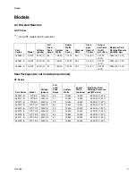
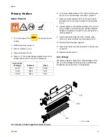
Summary of Contents for Reactor HT Series
Page 43: ...Parts 312408F 43 ...


