
Repair
26
312408F
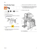
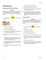
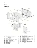
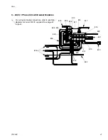
Display Module
Temperature and Pressure Displays
1.
Turn main power OFF
. Disconnect power
supply.
2.
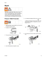
Relieve pressure, page 15.
3.
Refer to electrical diagrams.
4.
Put on static conductive wrist strap.
5.
Disconnect main display cable (20) at lower left cor-
ner of display module; see F
IG
. 10.
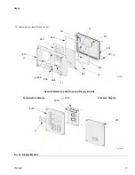
6.
Remove screws (509, 510) and cover (504); see
F
IG
. 10.
7.
Disconnect cable connectors J1 and J13 from back
of temperature display (501) or pressure display
(502); see F
IG
. 10.
8.
Disconnect ribbon cable(s) (R) from back of display;
see F
IG
. 10.
9.
Remove nuts (508) and plate (505).
10. Disassemble display, see detail in F
IG
. 10.
11. Replace board (501a or 502a) or membrane switch
(501b or 502b) as necessary.
12. Reassemble in reverse order, see F
IG
. 10. Apply
medium strength thread sealant where shown. Be
sure display cable ground wire (G) is secured
between cable bushing and cover (504) with screws
(512).
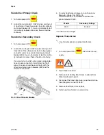
Red Stop Button
1.
Turn main power OFF
. Disconnect power
supply.
2.
Relieve pressure, page 15.
3.
Refer to electrical diagrams.
4.
Put on static conductive wrist strap.
5.
Remove screws (509, 510) and cover (504), F
IG
. 10.
6.
Disconnect button cable connectors (506) from back
of temperature display (501) and pressure display
(502).
7.
Remove red stop button (506).
8.
Reassemble in reverse order. Be sure display cable
ground wire (G) is secured between cable bushing
and cover (504) with screws (512).
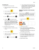
CAUTION
Before handling board, put on a static conductive wrist
strap to protect against static discharge which can
damage board. Follow instructions provided with wrist
strap.
If replacing both displays, label temperature display
cables TEMP and cycle counter display cables
CYCLES before disconnecting.
CAUTION
Before handling board, put on a static conductive wrist
strap to protect against static discharge which can
damage board. Follow instructions provided with wrist
strap.
Summary of Contents for Reactor HT Series
Page 43: ...Parts 312408F 43 ...


