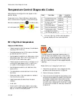
Communication Diagnostic Code
312408F
9
b.
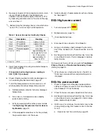
Perform Transformer Primary Check and
Transformer Secondary Check, starting on
page 25.
E04: Fluid Temperature Sensor
(FTS) or thermocouple
disconnected
1.
Check temperature sensor connections to long
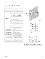
green connector (B) on temperature control module,
page 19. Unplug and re-plug sensor wires.
2.
Test fluid temperature sensor continuity with ohm-
meter, page 8.
3.
If an error occurred for the hose zone, check FTS
connections at each section of hose.
4.
If an error occurred for the hose zone, test FTS by
plugging directly into machine.
5.
To verify heater control module is not causing the
problem, use a wire to short-circuit the two pins cor-
responding to the FTS (red and yellow for A or B
zone, red and purple for hose). The display will
show the control heater module temperature.
6.
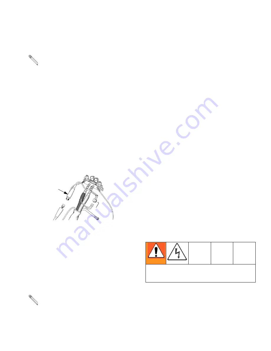
If an error occurred for the hose zone, temporarily
use the current control mode. Refer to Reactor
Operation manual 312407.
E05: Circuit board overheated
1.
Check that fan above electrical cabinet is operating.
2.
Check that electrical cabinet door is properly
installed.
3.
Check for obstructions blocking cooling holes in bot-
tom of electrical cabinet.
4.
Clean heatsink fins behind heater control modules.
5.
Ambient temperature may be too high. Allow Reac-
tor to cool by moving to a cooler location.
E06: Communication cable
unplugged
1.
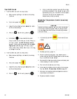
Unplug and re-plug cable that connects heater con-
trol module to heater module.
2.
Replace communication cable if problem persists.
Communication
Diagnostic Code
E99: Loss of communication
Communications between the display and the motor
control board or the temperature control board has been
lost. When communication is lost, the corresponding
display will show E99.
1.
Check all wiring between the display and the corre-
sponding control board. Pay close attention to the
wire crimping on plug J13 for each board.
2.
Measure the incoming voltage to the board (it
should be ~ 230Vac).
3.
If it was only receiving 1 leg of the 230Vac the board
may light up, and still not function properly. Correct
the incoming voltage problem.
When a no current error occurs, the LED on the
specific zone’s module turns red when the error is
displayed.
Each module has an on-board temperature sensor.
Heat is turned off if module temperature exceeds
185°F (85°C) within the heater module.
ti9878a
F
Step 2 measures line voltage and should be done by a
qualified electrician. If work is not performed properly
it may cause electric shock or other serious injury.
Summary of Contents for Reactor HT Series
Page 43: ...Parts 312408F 43 ...


