
17
309977
Pressure Control Repair
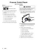
Pressure Control Transducer
Removal
Refer to
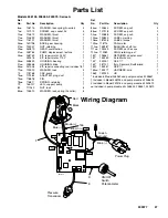
Wiring Diagram
, page 27.
1.
Relieve pressure
;
page 4.
2.
Remove five screws (12) and motor cover (18).
3.
Disconnect lead (E) from motor control
board (38).
4.
Remove strain relief (49) from circuit board bracket
(21). Thread transducer connector through
bracket.
5.
Remove pressure control transducer (43) and
packing o-ring (89) from pump housing (202).
Installation
1.
Install packing o-ring (89) and pressure control
transducer (43) in pump housing (202). Torque to
30–35 ft-lb.
2.
Thread transducer connector through circuit board
bracket (21). Install strain relief (49) in circuit board
bracket.
3.
Connect lead (E) to motor control board (38).
4.
Install motor cover (18) with five screws (12).
Pressure Adjust Potentiometer
Removal
Refer to
Wiring Diagram
, page 27.
1.
Relieve pressure
;
page 4.
2.
Remove five screws (12) and motor cover (18).
3.
Disconnect potentiometer lead (47) from motor
control board (38).
4.
Remove potentiometer knob (16), gasket (88) and
pressure adjust potentiometer (47).
Installation
1.
Install pressure adjust potentiometer (47), gasket
(88) and potentiometer knob (16).
a.
Turn potentiometer fully clockwise.
b.
Install knob at full clockwise position.
2.
Connect potentiometer lead (47) to motor control
board (38).
3.
Install motor cover (18) with five screws (12).
Summary of Contents for T-Max 405 248195
Page 30: ...30 309977 Notes ...


