


Setup/Startup
10
3A8108A
Tape and Roller Setup
Accurate tape and roller setup is essential to
ensuring that the tape properly aligns into
road inlay grooves and to ensure rollers
remain free from adhesive primer. Failure to
properly set the tape and rollers could make
taping difficult.
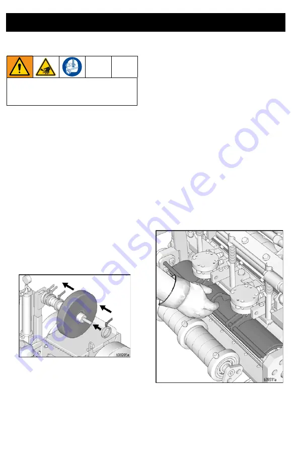
Loading Tape
1.
Perform pressure relief procedure, see
2.
Remove end collar from tape support
spindle.
3.
Align inside collar in proper location
along spindle, depending on the width of
the tape, to position it correctly on the
spindle.
4.
Lock inside collar into position.
5.
Load tape onto spindle so that the tape
feeds from the bottom of the roll.
6.
Re-install end collar.
NOTE:
It is critical that the tape remain in
tension during the application process. Prior
to locking the end collar into place, press the
collar into the tape roll so that the tape does
not feed too fast during high speed
applications.
7.
Lock end collar into position.
8.
Adjust the collars on the tape guide roller
and the segments on the applicator and
tamping rollers to match the position and
width of the tape, see
, page 11. Matching lines
are provided on the rollers to allow for
easy alignment of tape.
NOTE:
Applicator and tamping rollers should
be set up to match the width of the tape. If
rollers are wider than the tape, the tape may
not properly affix into road inlay grooves.
NOTE:
It may be helpful to lift the brake (as
shown below) before feeding tape, or if tape
is difficult to pass through the rollers.
To help prevent injury from cutting, install
the blade guard or remove blade prior to
adjusting rollers.
Summary of Contents for TapeLazer HP Automatic
Page 15: ...Setup Startup 3A8108A 15 7 Using a 1 4 in Allen wrench tighten bolts ...
Page 25: ...Operation 3A8108A 25 TapeLazer LiveLook Display ...
Page 51: ...Troubleshooting 3A8108A 51 Solenoid Ports Reference ...
Page 52: ...Parts 52 3A8108A Parts TapeLazer Parts ...
Page 54: ...Parts 54 3A8108A Front End Parts ...
Page 56: ...Parts 56 3A8108A Carriage Applicator Parts ...
Page 58: ...Parts 58 3A8108A Display Unit Parts ...
Page 60: ...Parts 60 3A8108A Additional Parts ...
Page 62: ...Air Line Schematic 62 3A8108A Air Line Schematic ...
Page 64: ...Wiring Diagram 64 3A8108A Wiring Diagram ...
Page 65: ...Universal Symbols Key 3A8108A 65 Universal Symbols Key ...


