background image

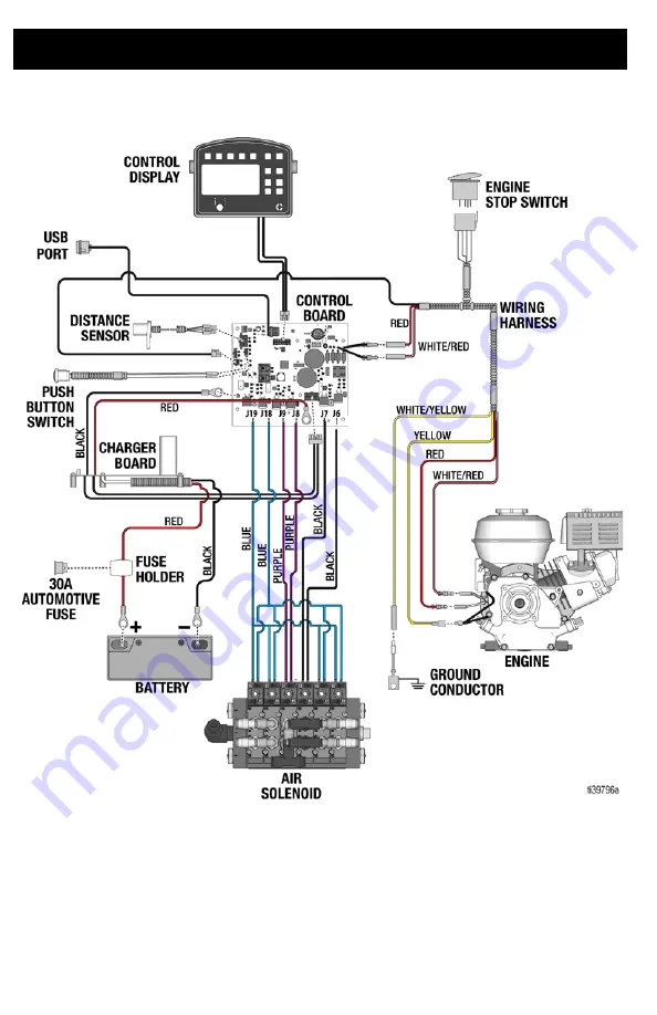
Wiring Diagram 

64

3A8108A

Wiring Diagram

Summary of Contents for TapeLazer HP Automatic

Page 1: ...only For outdoor use only Not approved for use in explosive atmosphere or hazardous classified locations 145 psi 1 0 MPa 10 0 bar Maximum Working Pressure Models 20A024 20A140 Important Safety Instructions Read all warnings and instructions in this manual and related manuals before using the equipment Save these instructions ...

Page 2: ...ositions 24 TapeLazer LiveLook Display 25 Applying Tape 26 System Delay 27 Operating System Delay 27 System Delay Example Semi Auto Mode Skip Line 28 System Delay Example Auto Mode Skip Line 29 System Delay Example Manual Mode Skip Line 30 System Delay Example Semi Auto and Auto Mode Solid Line 31 System Delay Example Manual Mode Solid Line 32 Cut Delay 33 Measure Mode 34 Splicing Tape 35 Setup In...

Page 3: ...t Description Maximum Working Pressure psi MPa bar Approvals 20A024 TapeLazer HP Automatic 145 psi 1 MPa 10 0 bar 20A140 TapeLazer HP Automatic with LazerGuide 3000 Manual in English Description 312540 LineDriver Operations Parts and Repair Manual 3A6623 LineDriver ES Operations Parts and Repair Manual 3A5294 LazerGuide Instructions 37Z4V611 Honda Engine Manual ...

Page 4: ...vices MUTCD U S Department of Transportation Federal Highway Administration or local regulations FIRE AND EXPLOSION HAZARD Flammable fumes in work area can ignite or explode To help prevent fire and explosion Use equipment only in well ventilated area Do not fill fuel tank while engine is running or hot shut off engine and let it cool Fuel is flammable and can ignite or explode if spilled on hot s...

Page 5: ...shine the laser at mirror like surfaces which can cause specular reflections of the beam Always set the laser at a height and angle that prevents the beam from shining into people s eyes Immediately terminate laser emissions if personnel animals or reflective objects approach the beam Always turn off laser when unattended Do not remove any warning labels from the laser Only properly trained laser ...

Page 6: ...oad 4 Engine throttle 5 Carriage locking pin 6 Tape roll support spindle 7 Air drain valve 8 Cutting blade 9 Tape brake roller 10 12 volt battery 11 Handlebar 12 Front wheel release lever 13 Identification label 14 Tape application button 15 Carriage 16 LineDriver hitch 17 Parking brake 18 Tape brake 19 Tape application assembly 20 Solenoid manifold ...

Page 7: ...s turned off 2 Lock carriage in the up position by turning and pushing locking pins in on both sides of the carriage 3 Open air drain valve as shown to relieve air pressure This equipment stays pressurized until pressure is manually relieved To help prevent serious injury from moving parts follow the pressure relief procedure before cleaning checking or servicing the equipment ...

Page 8: ...uel tank 4 Remove blade guard See Blade Guard Removal and Installation page 14 Connecting a LineDriver It is recommended to use a LineDriver in conjunction with the TapeLazer To connect the TapeLazer to a LineDriver follow the steps below 1 Install LineDriver coupler to TapeLazer hitch ball 2 Latch coupler to locked position 3 Insert safety pin into latch To help prevent serious injury from pinchi...

Page 9: ...To help reduce fatigue adjust one pedal for a full motion forward and one for full motion in reverse 5 Loosen two bolts on topside of pedals on LineDriver 6 Rotate pedal on LineDriver to desired position Tighten bolts 7 See LineDriver manual for instructions on starting and operating LineDriver ...

Page 10: ...that the tape remain in tension during the application process Prior to locking the end collar into place press the collar into the tape roll so that the tape does not feed too fast during high speed applications 7 Lock end collar into position 8 Adjust the collars on the tape guide roller and the segments on the applicator and tamping rollers to match the position and width of the tape see Roller...

Page 11: ...d Roller Adjustment 1 Perform pressure relief procedure see Pressure Relief Procedure page 7 2 Using a 1 4 in Allen wrench adjust the tape collars on the guide roller to match the width and position of the tape NOTE It is recommended you either have the blade guard in place or remove the blade prior to removing the applicator roller See Blade Guard Removal and Installation page 14 3 Remove front b...

Page 12: ...ex shaft Loosen set screws in rollers to remove or adjust them to the necessary width and location to match the tape NOTE Removed rollers can be stored on the vertical posts located in front of the handlebars 7 Tighten set screws on roller segments once in place and re install bolt on end of hex shaft 8 Re install applicator roller plate and bolts Tighten bolts with 1 4 in Allen wrench 9 Rotate th...

Page 13: ... remove or adjust them to the necessary width and location to match the tape NOTE Removed rollers can be stored on the vertical posts located in front of the handlebars 12 Tighten set screws on all roller segments once in place and re install bolt on the end of hex shaft 13 Re install tamping roller plate and bolts Tighten bolts with 1 4 in Allen wrench ...

Page 14: ...a1 4 in Allenwrench loosenbolts holding blade guard in place on both sides of the unit 3 Remove blade guard 4 Tighten bolts 5 To re install use 1 4 in Allen wrench to loosen bolts holding the blade in place 6 Carefully re install blade guard To help prevent injury from cutting install the blade guard or remove blade prior to adjusting rollers ...

Page 15: ...Setup Startup 3A8108A 15 7 Using a 1 4 in Allen wrench tighten bolts ...

Page 16: ...eTapeLazer 2 Slide carriage left or right to the desired location NOTE Have a second person push down on the TapeLazer handlebars to relieve tension on the bolts while you slide the carriage right or left 3 Notches are set in the carriage and frame at one inch intervals which match the lines on rollers to help with alignment A larger center notch allows for easy reorientation to the center positio...

Page 17: ...lignment To properly align the front wheels perform the following steps 1 Loosen bolt on the front wheel bracket 2 If taper arcs to the right loosen left set screw and tighten right set screw for fine tune adjustment 3 If taper arcs to the left loosen right set screw and tighten left set screw 4 Roll the taper Repeat steps 2 and 3 until taper rolls straight Tighten bolt on wheel alignment plate to...

Page 18: ...tilt use a 3 4 in wrench to loosen the four bolts two on each side holding the handlebars to the display unit 2 Tilt handlebars until they are in the desired location 3 Re tighten bolts 1 To adjust the height of handlebars use a 3 4 in wrench to loosen the four bolts two on each side holding the handlebars to the frame of the unit 2 Slide handlebars and up or down to set the desired height 3 Re ti...

Page 19: ...t 1 Perform Pressure Relief Procedure page 7 2 Move fuel valve to open 3 Move choke to closed 4 Set throttle to fast 5 Set engine switch to on 6 Pull starter cord 7 After engine starts move choke to open 8 Set throttle to desired setting ...

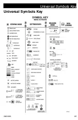
Page 20: ...tions Language From SETUP INFO select appropriate language by pressing D until the language is outlined ENG English SPA Spanish FRE French DEU German RUS Russian WORLD Symbols see Universal Symbols Key page 65 NOTE The default language can be changed at any time Time and Date and Distance Units Press SETTINGS B from the SETUP INFO screen to access Time and Date and Distance Units Press A to adjust...

Page 21: ...sary 2 Extend steel tape to 25 ft 8 m or longer 3 Move pointer to rear position 4 Press to select SETUP INFO 5 Press for Calibration Set TRAVEL DIST to 24 ft 7 m or longer Longer distances ensure better accuracy depending on conditions 6 Setguide andalign with onefootmarkon steel tape as shown in picture ...

Page 22: ...igns with 25 ft mark on steel tape a total traveled distance of 24 ft or to whatever distance you entered on the screen 10 Press and release tape application button to complete calibration NOTE Calibration is NOT complete when the exclamation symbol is displayed NOTE Calibration is finished when the check mark symbol is displayed 11 Calibration is now complete ...

Page 23: ...tance is also adjusted to maintain the set cycle length sum of the skip and space lengths Discrepancies with line length accuracy especially in AUTO MODE can be improved by adding weight in the on board payload compartment between the rear axle DO NOT add weight to the front of the TapeLazer as this will cause the rear tire to lose connectiontothepavementcausingloss of wheel sensor accuracy Refer ...

Page 24: ...sitions may be relevantwhen operating repairing or assessing the TapeLazer Application Position Secondary Position Cut Position In addition the TapeLazer Carriage uses two positions during operation raised and lowered These positions may be relevant when operating repairing or assessing the TapeLazer Carriage Raised Carriage Lowered ...

Page 25: ...Operation 3A8108A 25 TapeLazer LiveLook Display ...

Page 26: ...age 19 2 Close air drain valve as shown to pressurize the system 3 Unlock the locking pins on both sides of the carriage 4 Press the carriage raise lower and engine stop button to lower the carriage 5 Move forward and presstape application button to start applying tape ...

Page 27: ... 2 With System Delay the pointer A becomes the initiation point for all starts and stops activated by the tape application button 3 Choose Line Type SOLID or SKIP Line Type is indicated by LED after selection 4 Choose Mode Manual M Semi Auto S or Auto A 5 Example below when the pointer A reaches start point B press or hold in manual mode the tape application button When the pointer reaches the end...

Page 28: ... at that point except if the pointer is less than 1 foot from the start of the line B the button press will be ignored with a message on the screen The operator will need to travel further before pressing the button to end the line NOTE The minimum achievable space between intermittent lines is approximately 1 ft If the button press to start a new line is less than one foot from the end of the pre...

Page 29: ... if the pointer is less than 1 foot from the start of the line B the button press will be ignored with a message on the screen The operator will need to travel further before pressing the button to end the line After pressing the button a second time either after D or before C the operator can press the button again to start another set of skips However if the press occurs less than 1 from the pre...

Page 30: ...tion when the spacing between lines remains consistent Option 2 Press and HOLD tape application button when pointer A reaches beginning of skip line start point B Release auto tape control button when pointer reaches end of skip line C Repeat this process for all skip line placement This is similar to Semi Auto skip line placement Use this option when the spacing between lines varies Tape Interrup...

Page 31: ... application button function for continuous line placement is identical to AUTO MODE Press and RELEASE tape application button when pointer A reaches start of line B Press and RELEASE auto tape application button a second time at the end of continuous line D Tape Interrupt All system delay operation can be canceled by turning System Delay OFF turning the LINE TYPE button off both LEDs off or doubl...

Page 32: ... Application Button activity Press and HOLD tape application button when pointer A reaches start of line B Release tape application button at the end of the continuous line D Tape Interrupt All system delay operation can be canceled by turning System Delay OFF turning the LINE TYPE button off both LEDs off or double pressing the tape application button ...

Page 33: ...t is pre set for best results but adjustments might be required from time to time If the skip line is longer or shorter than the displayed value follow the steps below 1 Negative Tape Cut Delay X is used when actual tape length is longer than programmed length Decreasing Tape Cut Delay will reduce tape length 2 Positive Tape Cut Delay X is used when actual tape length is shorter than programmed le...

Page 34: ...s and release tape application button Move taper forwards or backwards NOTE Moving backwards displays a negative distance 3 Press and release tape application button to end measured length Up to six lengths are viewable Ref Description 1 Press to start measurement Press to stop measurement 2 Hold to reset values to zero 3 Scroll between main menu screens 4 Last measurement taken ...

Page 35: ...lers 2 Peel remaining tape from roll and prevent it from becoming dirty or otherwise compromised 3 Install new tape on tape roll spindle see Loading Tape page 10 4 Peel end of the tape from the new roll and match the ends of each tape roll Apply splicing tape to tape seam 5 Roll tape back onto the spindle to create tension on tape 6 Resume taping ...

Page 36: ...ls Key page 65 for explanation of screen symbols Press to select Calibration See Calibration page 21 Press to select Settings See Settings page 37 Press to select Information See Information page 38 Press to select Language See Language page 20 Press to select Cut Delay See Cut Delay page 33 ...

Page 37: ...Key page 65 for explanation of screen symbols Press to open Time an Date Set Time an Date on this screen This is needed for accurate Data Logging Press to set Units as feet or meters Press to set Contrast Adjustment Adjust screen contrast to desired value Press to choose start programmed lines with Skip or Space ...

Page 38: ...battery and charger information and provide a live look at which outputs are operating properly or are open short Diagnostic screen 3 displays each output s approximate current and duty cycle Control board outputs affect the following solenoids as referenced by labelonsolenoidassembly seeAirLine Schematic page 62 and Solenoid Locations on Control Board page 48 Press to open the error screen This s...

Page 39: ...bols Key page 65 for explanation of screen symbols Press the to open the Data Logging pop up window Choose to start recording a new job or view jobs previously done Start recording a new job Erase all jobs Export all jobs to USB Erase displayed job Export job to USB Job data is compiled while taping It keeps track of distance taped tape color and line width but tracks skips and solids separately ...

Page 40: ...on threads To check oil level 1 If unit is equipped with drain plug remove drain plug and verify oil is visible on threads of drain port If not full fill with oil through drain port until visible on threads 2 If unit is equipped with sight glass verify oil level is above red dot If not remove oil breather and fill with oil through breather port until level is above red dot NOTE Oil level will chan...

Page 41: ...move it NOTE Blade may become stuck from rust or debris If blade is stuck remove bolt on opposite side of the unit and place new blade against the old one Using a hammer gently tap new blade into place pushing the old blade out the opposite side 4 Install new blade into place 5 Usinga1 4in Allenwrench reinstallbolt and washers holding blade in place To help prevent serious injury from cutting wear...

Page 42: ... Remove two pins holding brake in place Set aside to reuse 3 Using a 1 4 inch Allen wrench remove four bolts and washers two on each side 4 Pivot brake forward and remove 5 Replace brake and re attach four bolts and washers 6 Replace pins To help prevent injury install the blade guard or remove blade prior to adjusting rollers ...

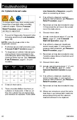
Page 43: ...lieve air pressure see Pressure Relief Procedure page 7 High engine speed at no load Mis adjusted throttle setting Reset throttle to 3000 engine RPM at no load Worn engine governor Replace or service engine governor Refer to Honda Engines Owner s Man ual Distance not adding properly measure mode and speed will be inaccurate Unit is not calibrated Re calibrate unit See Calibration page 21 Pavement ...

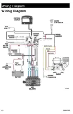
Page 44: ...ard With engine running check voltage to control board at red and red white wires See Wiring Diagram page 64 If voltage is present replace board If no voltage check for voltage from gray engine leads where red and white red wires connect If not voltage there consult Honda engine owner s manual If voltage exists there replace wiring harness Control board faulty Wiring harness is faulty Will not lay...

Page 45: ...f necessary Will not lower carriage Mechanical lock s engaged Disengage the mechanical lock s Control board output 3 is shorted Check for faulty connection Replace solenoid if necessary Refer to unit error screen See To Check if Solenoids are Functioning Properly page 49 Control board output 3 is open Tape carriage button is not connected Check for faulty connection Replace switch if necessary Wil...

Page 46: ...on assembly is in cut position Carriage is in the lowered position see Tape Application Assembly Positions page 24 Output 1 OFF Output 2 OFF Output C ON To help prevent injury from moving parts keep clear of carriage when actuating solenoid outputs Perform Pressure Relief Procedure page 7 before working on equipment Operating Condition Output 1 Output 2 Output C Description 1 Off Off Off Tape appl...

Page 47: ...put C use the carriage raise lower switch 4 To energize outputs 1 and 2 either solid or skip line must be selected and highlighted red on the display If unit does not function as described above check the following 1 Mechanical jam Check to make sure there is no obstruction or binding that is restricting movement Make sure that the carriage locking pins are in the retracted position 2 Wiring is in...

Page 48: ...ol board outputs 1 2 and C see Solenoid Locations on Control Board page 48 3 Navigate to Diagnostic Screen 2 on control display see Information page 38 4 Actuate outputs 1 2 and C see the Notes page 47 under Solenoid Manifold Operation page 46 5 Measure the DC voltage across the three solenoid outputs 6 If control board voltages are in this range the control board is good The solenoid manifold nee...

Page 49: ...ssor fan to be in motion while the unit is running a Compressor is outputting air there is a leak elsewhere in the system Proceed with step 4 b Compressor is not outputting air compressor has failed Replace compressor and follow recommended maintenance intervals to prevent future failure 4 Close off system by turning pressure relief valve shut and check for external leaks There should be no air le...

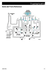
Page 50: ...e 8 Close air drain valve 9 Actuate control board output C see the Notes page 47 under Solenoid Manifold Operation page 46 10 If no airflow is observed deactivate control board output C and preform pressure relief procedure see Pressure Relief Procedure page 7 11 Reconnect air lines disconnected in step 7 and disconnect those in the third row of the table above 12 Close air drain valve 13 Actuate ...

Page 51: ...Troubleshooting 3A8108A 51 Solenoid Ports Reference ...

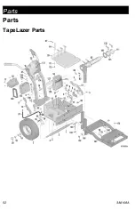
Page 52: ...Parts 52 3A8108A Parts TapeLazer Parts ...

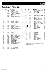
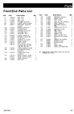
Page 53: ...R distance 1 38 108868 CLAMP wire 1 39 260212 SCREW hex washer hd 1 50 155500 PACKING O ring 1 51 108851 WASHER plain 10 52 20A473 SHELF battery 1 53 17K377 COVER pointed 1 64 18C716 SHAFT roller holder 4 67 123906 PIN cotter hairpin 4 68 18C632 FRAME front painted 1 71 116913 BALL trailer includes nut and lock washer 1 77 18C667 BOLT carriage 4 78 109052 WASHER plain 4 79 101580 NUT lock 4 82 18C...

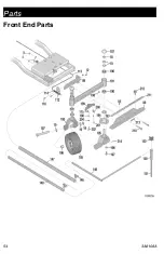
Page 54: ...Parts 54 3A8108A Front End Parts ...

Page 55: ...ter includes 146 147 148 149 150 151 152 1 148 17H438 TUBE weldment pointer 1 149 17H441 EXTENSION pointer weldment 1 150 17H445 TUBE pointer hose weldment 1 151 17H719 HOSE pointer 1 pack 1 24Y511 HOSE pointer 5 pack 1 152 114966 KNOB pronged 1 187 114648 CAP dust 2 190 113485 BEARING cup cone 4 191 18C620 FRAME caster 1 193 113484 SEAL grease 2 194 17H486 DISK adjuster assembly 1 195 17H485 FORK...

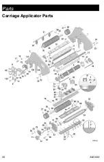
Page 56: ...Parts 56 3A8108A Carriage Applicator Parts ...

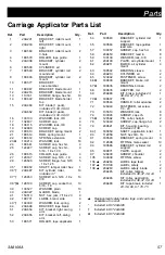
Page 57: ...00527 WASHER plain 10 40 20A327 GUARD blade 1 41 150513 NUT hex jam 7 16 x 20 4 42 18C731 LABEL brand side 4 43 104008 WASHER lock spring 2 44 20A648 BRACKET tape break 1 51 20A654 KIT bracket right swing arm 1 52 20A655 KIT bracket left swing arm 1 53 18C571 ROLLER tape applicator 1 54 18C583 BRACKET cylinder rod support 1 55 18C584 BRACKET tape guides lead wire 1 57 100057 SCREW cap hex hd 8 58 ...

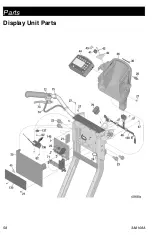
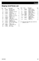
Page 58: ...Parts 58 3A8108A Display Unit Parts ...

Page 59: ...L USB 1 41 17Z084 KIT board USB includes 40 42 43 1 42 17V519 SCREW pan hd 2 43 131718 COVER dust USB 2 44 20A659 KIT box display includes 28 1 45 189930 LABEL caution 1 46 128856 CLAMP cable nylon 2 47 115483 NUT lock 2 62 111280 NUT locking 5 70 128783 SWITCH rocker 1 71 25A495 KIT board charger battery includes 62 1 72 15K162 BLOCK switch 1 73 194310 LEVER actuator 1 74 17J236 SWITCH pushbutton...

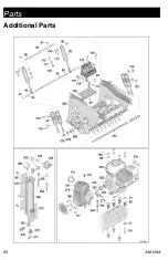
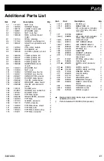
Page 60: ...Parts 60 3A8108A Additional Parts ...

Page 61: ...e 1 159 C19817 SCREW cap socket hd 2 163 187357 ELBOW street 3 164 156971 FITTING nipple 1 165 20A206 REGULATOR unloader 1 166 162453 FITTING 2 168 101180 GAUGE pressure 1 169 16U174 TANK pressure 1 170 100839 FITTING elbow street 4 171 20A644 FITTING tube 2 172 125423 FITTING reducer plug 2 173 115671 FITTING connector 2 174 25R115 FILTER air 1 175 25R114 BREATHER oil 1 176 19C950 KIT compressor ...

Page 62: ...Air Line Schematic 62 3A8108A Air Line Schematic ...

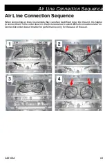
Page 63: ...n connecting air lines to solenoids they can often be difficult to lay into the unit It is helpful to connect them in the order shown in the pictures below to avoid difficult connections later on Connection order doesn t matter for performance only for the ease of the user ...

Page 64: ...Wiring Diagram 64 3A8108A Wiring Diagram ...

Page 65: ...Universal Symbols Key 3A8108A 65 Universal Symbols Key ...

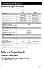
Page 66: ... Unpackaged 232 kg Packaged 278 kg Noise dBa Sound Power per ISO 3744 104 dBa Sound Pressure per ISO 3744 measured at 3 1 feet 1 0 m 84 dBa Vibration m s2 8 hours daily exposure Hand Arm per ISO 5349 TapeLazer Only Left hand 6 2 Right hand 5 4 TapeLazer Coupled to Gas LineDriver Left hand 6 5 Right hand 5 6 Power Rating Horsepower Power Rating Horsepower per SAE J1349 5 5 HP 3600 rpm 4 1 kW 3600 r...

Page 67: ...s of parts labor and transportation THIS WARRANTY IS EXCLUSIVE AND IS IN LIEU OF ANY OTHER WARRANTIES EXPRESS OR IMPLIED INCLUDING BUT NOT LIMITED TO WARRANTY OF MERCHANTABILITY OR WARRANTY OF FITNESS FOR A PARTICULAR PURPOSE Graco s sole obligation and buyer s sole remedy for any breach of warranty shall be as set forth above The buyer agrees that no other remedy including but not limited to inci...

Page 68: ...polis International Offices Belgium China Japan Korea GRACO INC AND SUBSIDIARIES P O BOX 1441 MINNEAPOLIS MN 55440 1441 USA Copyright 2021 Graco Inc All Graco manufacturing locations are registered to ISO 9001 www graco com Revision A April 2021 Graco Information For the latest information about Graco products visit www graco com For patent information see www graco com patents TO PLACE AN ORDER c...

Reviews: