background image

Spray

Spray

Spray

Spray

NOTICE

NOTICE

NOTICE

Do not operate the pump motor with the applicator
material ball valve (V) closed. This may cause the
pump or hose to pack out.

Prevent

Prevent

Prevent Packout

Packout

Packout

To avoid “packing out” the pump or hose:

• Use the lowest pressure and largest nozzle size

that provides an acceptable spray pattern. This will
also result in seals and wear parts lasting much
longer.

• Do not use any more fluid hose than is necessary.

• Use an applicator with a rubber tip retainer that will

blow off if it plugs.

Before

Before

Before Starting

Starting

Starting or

or

or Stopping

Stopping

Stopping Material

Material

Material

Flow

Flow

Flow

• Never dead end the pump against the fluid shut-off

ball valve.

• Start and stop the fluid flow with the red-handled

brass air motor pilot valve at the applicator.

• Always have the atomizing air turned on before

and after spraying fluid.

Before

Before

Before Starting

Starting

Starting Material

Material

Material Flow

Flow

Flow

1.

Always open the air assist valve (U) and adjust
air assist needle valve (M) first.

2.

Open applicator material ball valve (V) second.

3.

Open (turn on) the motor pilot ball valve (G) last.

Before

Before

Before Stopping

Stopping

Stopping Material

Material

Material Flow

Flow

Flow

1.

Always close (turn off) the motor pilot ball valve
(G) first.

2.

Close applicator material ball valve (V) second.

3.

Turn off the air assist valve (U) last.

Spraying

Spraying

Spraying

NOTICE

NOTICE

NOTICE

Do not allow pump to run without material in the
hopper. It will quickly accelerate to a high speed
causing pump seal damage.

NOTICE

NOTICE

NOTICE

To prevent material curing in system, never load
mortar into a dry system. Loading mortar into
a dry system will cause the mortar to stick to
internal components and cure causing damage
and requiring replacement of those parts.

1.

Wet Out the System, page 16

.

2.

Mix the Material, page 19

.

3.

Prime with Mortar or Epoxy, page 20

.

NOTICE

NOTICE

NOTICE

Failure to flush prior to material curing in the
system will result in damage to system and
may require replacement of all system parts in
contact with the material.

4.

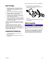
Turn air regulator adjustment knob (F)
counterclockwise until it stops and gauge (E)
reads zero.

E

F

ti21571a

Figure 25

22

332612C

Summary of Contents for ToughTek M680a

Page 1: ... mastics mastics mastics and and and epoxies epoxies epoxies For For For professional professional professional use use use only only only Important Important Important Safety Safety Safety Instructions Instructions Instructions Read all warnings and instructions in all manuals Save Save Save all all all instructions instructions instructions See page 6 for models and approvals information 1000 ps...

Page 2: ...ay Adjustments HTX 680 Applicator 26 Flush 27 Disassemble and Clean the Pump Daily 30 Shutdown 33 Maintenance 33 Preventative Maintenance 33 Daily Maintenance 33 Corrosion Protection 34 Cart Maintenance 34 Troubleshooting 35 Repair 37 Replace Pump Components 37 Replace Air Motor 37 Replace Pump Lower 37 Parts 38 Accessories 44 Technical Specifications 45 Graco Standard Warranty 48 Related Related ...

Page 3: ...nt in the work area See Grounding Grounding Grounding instructions Use only grounded hoses Hold applicator firmly to side of grounded pail when triggering into pail Do not use pail liners unless they are antistatic or conductive Stop Stop Stop operation operation operation immediately immediately immediately if static sparking occurs or you feel a shock Do not use equipment until you identify and ...

Page 4: ... not kink or over bend hoses or use hoses to pull equipment Keep children and animals away from work area Comply with all applicable safety regulations MOVING MOVING MOVING PARTS PARTS PARTS HAZARD HAZARD HAZARD Moving parts can pinch cut or amputate fingers and other body parts Keep clear of moving parts Do not operate equipment with protective guards or covers removed Pressurized equipment can s...

Page 5: ...CE NOTICE Changing the material types used in your equipment requires special attention to avoid equipment damage and downtime When changing materials flush the equipment multiple times to ensure it is thoroughly clean Always clean the fluid inlet strainers after flushing Check with your material manufacturer for chemical compatibility When changing between epoxies and urethanes or polyureas disas...

Page 6: ...nd air lines 5 Flex applicator includes 23 in 58 cm flexible hose with cam lock fluid inlet angled spray head spray air volume control spray air shut off valve and motor pilot signal control valve adjustable position center air injection tube rubber tip retainer and include 3 tip sizes Flex applicator is for use in low pressure spraying of materials that pack out easily and that will be finish tro...

Page 7: ...Models Agency Agency Agency Approvals Approvals Approvals Model Model Model Certification Certification Certification 262927 262909 262926 24T834 24T835 24T836 24T837 II 2 G Ex h IIA T5 Gb 332612C 7 ...

Page 8: ... AK ti21568a Figure 1 Key Key Key AA Material Hopper AB Air Motor AC Lower AD Cart AE Applicator AF Material Hose connects pump to whip hose AG Material Whip Hose AH Air Supply to Applicator for Air Assist and Air Motor ON OFF Pilot Valve shown disconnected AI Return Air to Air Motor ON OFF Pilot Valve AJ System Air Inlet AK Optional hose extension 8 332612C ...

Page 9: ...ero Cavity Relief Valve K Air Assist Tube L Grounding Wire required see Grounding page 13 M Needle Valve for Air Assist Flow Control N Air Supply Quick Disconnect to Applicator Air Inlet Quick Disconnect W P Fluid Outlet 1 in Male Camlock Fitting R Packing Nut Wet Cup under Spring Guard S Air Assist Nozzle Position Adjustment Screw T Applicator Tip Assembly U Air Assist Shutoff Ball Valve V Applic...

Page 10: ...tor Applicator CC CD CE CF CB CA U M Figure 3 Key Key Key M Needle Valve for Air Assist Flow Control U Air Assist Shutoff Ball Valve CA Air Assist Air Line CB Air Needle adjustable position CC Air Needle Retaining Screw CD Fluid Housing CE Tip Nozzle CF Rubber Tip Retainer 10 332612C ...

Page 11: ...plicator Applicator Applicator DD DB DG DA DE DF U M DC Figure 4 Key Key Key M Needle Valve for Air Assist Flow Control U Air Assist Shutoff Ball Valve DA Air Assist Air Line DB Fluid and Air Manifold DC Tip Nozzle DD Tip Retainer DE Air Check Valve DF Fluid Inlet Swivel DG Handle 332612C 11 ...

Page 12: ...lve Valve C C C Automatically opens to relieve air pressure if set pressure exceeds preset limit Air Air Air Filter Filter Filter D D D Removes harmful dirt and water from compressed air supply Air Air Air Regulator Regulator Regulator Adjustment Adjustment Adjustment F F F Adjusts air pressure to the motor and fluid outlet pressure of pump Read air pressure on gauge E Zero Zero Zero Cavity Cavity...

Page 13: ...metal pails 1 Connect the ground wire L Part No 262908 to the ground stud on the air motor L ti21630a Grounding Wire Figure 5 2 Connect the other end of the ground wire to a true earth ground 3 Ground the object being sprayed fluid supply container and all other equipment in the work area Follow your local code Use only electrically conductive air and fluid hoses 4 Ground all solvent pails Use onl...

Page 14: ...9 8 Attach small air tube from hose bundle to air motor pilot ball valve G on applicator Use wrench to secure air tube in place See Details page 9 9 Wrap blue velcro camlock retaining straps around each camlock connection to secure Note NOTE NOTE NOTE This includes the two camlocks between the hopper and pump lower the camlock at the pump outlet the camlocks on the fluid hoses and the camlock on t...

Page 15: ...e 9 3 Set air regulator F to zero pressure 4 Hold applicator firmly against a grounded metal pail Open the material ball valve V on the base of the applicator ti21632a Figure 10 5 If you suspect the applicator tip or hose is completely clogged or that pressure has not been fully relieved after following the previous steps slowly open the zero cavity relief valve J at the pump outlet See Details pa...

Page 16: ...le concrete pump priming fluids are used depending on what material is being sprayed Use the material flushing agent recommended on the material application data sheet When finished pump out the excess fluid Then drain out remaining fluid by loosening the bottom cam fitting 1 Close the bleed type master air valve B B A ti21575a Figure 11 2 Remove tip from applicator 3 Partially fill the clean hopp...

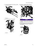
Page 17: ...Rotate the air regulator adjustment knob F clockwise until pump begins to move slowly F ti21570a Figure 16 NOTICE NOTICE NOTICE To prevent damage to pump seals caused by cavitation run the pump slowly until the system is primed 11 Continue running the pump until all of the flushing fluid is dispensed into the pail The system is now wetted out ti21632a Figure 17 332612C 17 ...

Page 18: ...m the system a Place grounded metal drain pan beneath pump lower inlet fittings b Remove hopper and fittings between hopper and pump lower c Use a screwdriver to lift the pump lower inlet ball This will drain the remaining material from the pump lower When the pump stops draining release the pump lower inlet ball d Install fittings and hopper e Install camlock retaining straps f Starting at the pu...

Page 19: ...tric drill Gear reduced drills work best Drill should have high torque at 300 1200 rpm A heavy duty drywall mud H blade or large Jiffy blade generally works well for mixing Note NOTE NOTE NOTE It will take most of the first batch of material to fill the pump and hoses Managing Managing Managing Mortar Mortar Mortar After After After Mixing Mixing Mixing Pay close attention to the work life of the ...

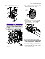
Page 20: ...mortar back into the hopper for a few minutes before beginning to spray 1 Wet out the system See Wet Out the System page 16 2 Mix the Material See Mix the Material page 19 3 Close the bleed type master air valve B B A ti21575a Figure 19 4 Remove tip from applicator 5 Fill the clean hopper with at least 4 gallons of the material to be sprayed If using 60 ft of material hose then fill with 6 gallons...

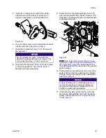
Page 21: ...l a steady stream of material comes from the applicator ti21632a Figure 23 13 To stop dispensing close the motor ON OFF pilot ball valve G Do not close the fluid ball valve V when the air motor is running ti21579a Figure 24 14 Place the applicator outlet into the hopper 15 With the fluid ball valve V open open the motor ON OFF pilot ball valve G Material will begin dispensing 16 Recirculate a few ...

Page 22: ...st valve U and adjust air assist needle valve M first 2 Open applicator material ball valve V second 3 Open turn on the motor pilot ball valve G last Before Before Before Stopping Stopping Stopping Material Material Material Flow Flow Flow 1 Always close turn off the motor pilot ball valve G first 2 Close applicator material ball valve V second 3 Turn off the air assist valve U last Spraying Spray...

Page 23: ...rial flow rate is achieved Turn clockwise to increase pressure counterclockwise to decrease pressure E F ti21571a1 Figure 27 NOTE NOTE NOTE See Spray Adjustments Mortar Spray Applicator page 24 or Spray Adjustments HTX 680 Applicator page 26for details about all of the adjustments that can be made to the way the system sprays 10 If the system is approaching its cure time or the system will be idle...

Page 24: ...ir Air Air Needle Needle Needle CB CB CB position position position Ensure the air needle CB is slightly behind the tip CE Note NOTE NOTE NOTE Installing needle too far forward can restrict or completely block material flow This can result in the retainer CF blowing off Installing the needle too far back can raise the pressure behind the fluid enough to blow the retainer CF off and can cause dripp...

Page 25: ...1 4 1 7 bar on the motor air regulator F Higher pressures may cause excessive wear on the fluid pump Select a fluid tip large enough to spray at low pressure Some materials will packout at higher pressures Installing Installing Installing Nozzle Nozzle Nozzle Retaining Retaining Retaining Cap Cap Cap 1 Place nozzle retaining cap over top lip of applicator housing 2 Insert screwdriver through hole ...

Page 26: ...ry for a good pattern Air bleeds from the applicator nozzle whenever the applicator air assist needle valve M is open Close the valve U to stop the majority of air flow if desired Some air will still bleed through valve U to help keep the air passages clean Otherwise the air valve U can stay open during priming Air must be on prior to any fluid flow Adjusting the spray pattern requires testing to ...

Page 27: ... decrease as this is a sign that material is starting to thicken and cure Always flush the system at least twice draining all material flushing agent between flushes then replacing with clean material flushing agent For some mortars it is recommended to flush every 3 5 kits Others can run continuously without flushing See material manufacturer recommendation 1 Close the bleed type master air valve...

Page 28: ...th clean water or solvent ti21644a Figure 36 b Use a scrub brush to scrub the walls of the hopper c Open the pilot ball valve G on applicator to begin circulating water or solvent d Run the pump at 60 90 cycles per minute for 3 5 minutes Adjust air pressure as necessary to maintain 60 90 cycles per minute Note NOTE NOTE NOTE High flushing fluid velocity is the most important item for effective cle...

Page 29: ...n hopper and pump lower c Use a screwdriver to lift the pump lower inlet ball This will drain the remaining material from the pump lower When the pump stops draining release the pump lower inlet ball d Install fittings and hopper e Install camlock retaining straps f Starting at the pump raise the hose bundle above your head and slowly move towards the applicator As you move towards the applicator ...

Page 30: ...ble Disassemble and and and Clean Clean Clean the the the Pump Pump Pump Daily Daily Daily Suggested Suggested Suggested Tools Tools Tools 5 8 in box end wrench or 5 8 in socket and ratchet Rubber mallet to break items loose if necessary Figure 37 30 332612C ...

Page 31: ...or applicator fitting while there is pressure in the fluid line See Pressure Relief Procedure page 15 See the figure at the beginning of this section for part references Disassemble and clean the pump at the end of every day The procedure takes about 10 minutes Note NOTE NOTE NOTE As items are disassembled use a soft brush and water or a compatible solvent to clean components 1 Flush the system Se...

Page 32: ... with o ring BT installed between outlet housing BK and cylinder BI Note NOTE NOTE NOTE If the o ring BT does not stay in place while assembling the cylinder BI to the housing BK the cart may need to be tipped upright to install properly After clamp is installed tip cart back to horizontal position to finish assembly 10 Use cylinder clamp BJ to secure cylinder BI to outlet housing BK Note NOTE NOT...

Page 33: ...cular system determine how often maintenance is required Establish a preventive maintenance schedule by recording when and what kind of maintenance is needed and then determine a regular schedule for checking your system Daily Daily Daily Maintenance Maintenance Maintenance 1 Flush the system See Flush page 27 2 Relieve pressure See Pressure Relief Procedure page 15 3 Perform the Disassemble and C...

Page 34: ... the displacement rod First flush with water or a compatible solvent then with oil Relieve the pressure but leave the oil in the pump to protect the parts from corrosion Cart Cart Cart Maintenance Maintenance Maintenance Periodically lubricate the axle between points A and B with lightweight oil See the following figure Keep the cart clean by wiping up spills daily using a compatible solvent B A t...

Page 35: ...on on on down stroke down stroke down stroke Open or worn intake valve Clear or service intake valve Output Output Output low low low on on on up stroke up stroke up stroke Open or worn piston valve or packings Clear piston valve replace packings Erratic Erratic Erratic accelerated accelerated accelerated speed speed speed Fluid supply exhausted clogged suction Refill hopper and prime pump Open or...

Page 36: ...material Reverse hose and try to push out bad material Some materials may need only 1 in inner diameter fluid line all the way to the applicator Material Material Material is is is too too too thick thick thick to to to push push push through through through hose hose hose without without without packing packing packing out out out 3 4 in x 10 ft whip hose is too restrictive Remove 3 4 in x 10 ft ...

Page 37: ...Align air motor with tie rods 42 then tighten tie rods to air motor 7 Tighten tie rod nuts 44 8 Connect pump rod See figure shown previously in this section 9 Connect small air tubes to air motor Replace Replace Replace Pump Pump Pump Lower Lower Lower Perform this procedure to replace the entire pump lower with a new or different pump lower To repair or replace any internal components in the pump...

Page 38: ...ds 3 Apply Apply Apply clear clear clear liquid liquid liquid petrolatum petrolatum petrolatum to to to axles axles axles 1 1 1 before before before assembling assembling assembling wheels wheels wheels 2 2 2 4 Pack Pack Pack grease grease grease around around around the the the end end end of of of the the the zero zero zero cavity cavity cavity relief relief relief valve valve valve in in in fro...

Page 39: ...line line line air air air 1 1 1 1 1 1 1 1 1 1 1 1 2 2 2 31 31 31 159841 159841 159841 BUSHING BUSHING BUSHING 3 8 3 8 3 8 x x x 1 4 1 4 1 4 in in in 1 1 1 1 1 1 1 1 1 1 1 1 2 2 2 32 32 32 169970 169970 169970 FITTING FITTING FITTING line line line air air air 1 1 1 1 1 1 1 1 1 1 1 1 2 2 2 33 33 33 24U209 24U209 24U209 APPLICATOR APPLICATOR APPLICATOR texture texture texture pole pole pole 1 1 1 1...

Page 40: ... 4 4 4 4 4 4 4 4 4 4 4 4 4 98 98 98 24T854 24T854 24T854 BUNDLE BUNDLE BUNDLE hose hose hose 35 35 35 ft ft ft 1 1 1 1 1 1 1 1 1 1 1 1 1 1 1 99 99 99 24R254 24R254 24R254 BUNDLE BUNDLE BUNDLE hose hose hose extension extension extension 25 25 25 ft ft ft 1 1 1 Replacement Replacement Replacement Danger Danger Danger and and and Warning Warning Warning labels labels labels tags tags tags and and an...

Page 41: ...209 209 209 113430 113430 113430 COUPLING COUPLING COUPLING universal universal universal 3 4 14 3 4 14 3 4 14 npt npt npt female female female 1 1 1 210 210 210 104267 104267 104267 REGULATOR REGULATOR REGULATOR air air air 1 1 1 211 211 211 16W146 16W146 16W146 VALVE VALVE VALVE 3 3 3 way way way pilot pilot pilot operated operated operated 1 1 1 212 212 212 BRACKET BRACKET BRACKET air air air c...

Page 42: ... ring ring 4 Torque Torque Torque to to to 95 105 95 105 95 105 in in in lb lb lb 10 7 11 9 10 7 11 9 10 7 11 9 N m N m N m Ref Ref Ref Part Part Part Description Description Description Qty Qty Qty 301 301 301 HOUSING HOUSING HOUSING end end end 1 1 1 302 302 302 16U807 16U807 16U807 STEM STEM STEM 1 1 1 303 303 303 15M189 15M189 15M189 SPACER SPACER SPACER backup backup backup seal seal seal 1 1...

Page 43: ...1 1 1 1 1 1 427 427 427 127232 127232 127232 VALVE VALVE VALVE ball ball ball 1 1 1 inch inch inch stainless stainless stainless steel steel steel 1000 1000 1000 psi psi psi 1 1 1 1 1 1 428 428 428 24T762 24T762 24T762 HOSE HOSE HOSE air air air and and and pilot pilot pilot in in in scuff scuff scuff jacket jacket jacket 38 38 38 ft ft ft 1 1 1 1 1 1 429 429 429 114958 114958 114958 STRAP STRAP S...

Page 44: ...t easily and that will be finish troweled The pole applicator is similar to the Flexible Applicator but with a pipe in place of the hose See manual 332767 Includes 30 in 76 cm aluminum pipe with cam lock fluid inlet Angled spray head Spray air volume control Spray shut off valve Motor pilot signal control valve Adjustable position center air injection tube Rubber tip retainer 4 different sized tip...

Page 45: ...e Male Fluid Outlet Size 1 npt f with a 1 in Cam and Groove Fitting Weight without fluid 250 lb with 25 ft of 1 in hose and 10 ft of 3 4 in hose 113 kg with 7 6 m of 25 mm hose and 3 0 m of 19 mm hose Sound Pressure 118 dB A Sound Power 118 dB A Dimensions Height 44 5 in 113 cm Width 27 5 in 70 cm Depth pump on cart only 32 in 81 cm Deep pump on cart with hopper 37 in 94 cm Maximum Maximum Maximum...

Page 46: ...00 400 600 800 1000 10 0 20 50 40 30 A E F G H B C D 0 1 2 3 4 5 6 7 8 9 10 Air Flow in Standard Cubic Feet Per Minute Flow Rate in Gallons Per Minute Ref Ref Ref Description Description Description A Fluid Pressure at 20 psi Air B Fluid Pressure at 40 psi Air C Fluid Pressure at 70 psi Air D Fluid Pressure at 100 psi Air E Air Consumption at 20 psi Air F Air Consumption at 40 psi Air G Air Consum...

Page 47: ... M680a M680a Applicator Applicator Applicator Air Air Air Consumption Consumption Consumption 100 psi feed to the machine Standard Cubic Feet Per Minute of Air Cubic Meters Per Hour 0 10 20 30 1 0 2 0 3 0 4 0 5 0 Needle Valve Turns Open from Closed 332612C 47 ...

Page 48: ...WARRANTY WARRANTY WARRANTY AND AND AND DISCLAIMS DISCLAIMS DISCLAIMS ALL ALL ALL IMPLIED IMPLIED IMPLIED WARRANTIES WARRANTIES WARRANTIES OF OF OF MERCHANTABILITY MERCHANTABILITY MERCHANTABILITY AND AND AND FITNESS FITNESS FITNESS FOR FOR FOR A A A PARTICULAR PARTICULAR PARTICULAR PURPOSE PURPOSE PURPOSE IN IN IN CONNECTION CONNECTION CONNECTION WITH WITH WITH ACCESSORIES ACCESSORIES ACCESSORIES E...

Reviews: