Disassemble and Clean the Pump (Daily)
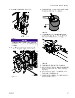
10. Disconnect pump rod (see the following figure):
a.
Push piston rod protective spring up and
away from coupling assembly (BF1-BF3).
b.
Remove clip (BF1), and slide coupling cover
(BF2) up to remove coupling (BF3).
BF3
BF2
BF1
ti21656a
Figure 39
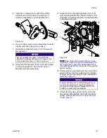
11. Pull rod (BF) down and out of outlet housing (BK).
12. Remove outlet ball stop (BG) from rod (BF) by
pushing o-rings off of ball stop (BG).
13. Loosen and remove packing nut (BM) then
remove throat packing (BL).
14. Use a brush and solvent to clean all loose pieces.
NOTE:
NOTE:
NOTE: The pump rod (BF) is not disassembled
unless the piston packing or seat needs to be
replaced.
NOTE:
NOTE:
NOTE: The inlet housing (BC) is not
disassembled unless the inlet seat needs to be
replaced.
Assemble
Assemble
Assemble the
the
the Pump
Pump
Pump
1.
Loosely install throat packing (BL) with the open
end facing into the pump.
2.
Install packing nut (BM) hand-tight.
3.
Lubricate the balls (BS, BD) to ensure they do
not stick.
4.
Install outlet ball (BS), outlet ball stop (BG) with
o-rings into rod (BF). Ensure outlet ball stop
o-rings are in the grooves on the outlet ball stop
rod.
5.
Grease the packing on the rod (BF).
6.
Gently slide rod (BF) through throat packing (BL).
7.
Install coupling (BF3), slide coupling cover (BF2)
over coupling, then install clip (BF1) to secure
pump rod (BF) to air motor.
8.
Use a flat-tip screwdriver and a plastic mallet to
tighten packing nut (BM) until it stops.
Note
NOTE:
NOTE:
NOTE: This is not an adjustable packing
but the packing nut (BM) does need to
be tight against the throat packing (BL).
9.
Slide cylinder (BI) over rod (BF) with o-ring (BT)
installed between outlet housing (BK) and
cylinder (BI).
Note
NOTE:
NOTE:
NOTE: If the o-ring (BT) does not stay in
place while assembling the cylinder (BI)
to the housing (BK), the cart may need
to be tipped upright to install properly.
After clamp is installed, tip cart back to
horizontal position to finish assembly.
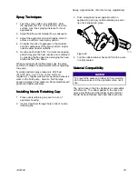
10. Use cylinder clamp (BJ) to secure cylinder (BI)
to outlet housing (BK).
Note
NOTE:
NOTE:
NOTE: Each clamp has one flat so that
only one wrench is required to tighten
clamp. Align bolt head with flat then
use a wrench on the nut to tighten.
Tighten both sides of the clamp evenly to
approximately 10 ft-lb (14 N•m).
11. Install inlet ball (BD), ball cage spring (BV), and
inlet ball stop (BE) in inlet housing (BC).
12. With inlet ball (BD), ball cage spring (BV), and
inlet ball stop (BE) in place, place o-ring (BT)
between cylinder (BI) and inlet housing (BC)
then use inlet housing clamp (BB) to install inlet
housing (BC) onto cylinder (BI).
Note
NOTE:
NOTE:
NOTE: Each clamp has one flat so that
only one wrench is required to tighten
clamp. Align bolt head with flat then
use a wrench on the nut to tighten.
Tighten both sides of the clamp evenly to
approximately 10 ft-lb (14 N•m).
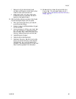
13. Install inlet elbow (BA) onto inlet housing (BC).
14. Tip cart up.
15. Install hopper (BN) onto the hopper bracket and
connect to inlet elbow (BA).
16. Install material hose onto pump outlet (BP).
17. Wrap blue, velcro, camlock retaining straps
around each camlock connection to secure.
Note
NOTE:
NOTE:
NOTE: This includes the two camlocks
between the hopper and pump lower, the
camlock at the pump outlet, the camlocks
on the fluid hoses, and the camlock on
the applicator inlet. The retaining straps
should be tight and must not be able to
slide off camlock.
18. Add TSL to the packing nut (BM) until 1/2 full.
32
332612C


