Spray
Spray
Spray
NOTICE
NOTICE
NOTICE
Do not operate the pump motor with the applicator
material ball valve (V) closed. This may cause the
pump or hose to pack out.
Prevent
Prevent
Prevent Packout
Packout
Packout
To avoid “packing out” the pump or hose:
• Use the lowest pressure and largest nozzle size
that provides an acceptable spray pattern. This will
also result in seals and wear parts lasting much
longer.
• Do not use any more fluid hose than is necessary.
• Use an applicator with a rubber tip retainer that will
blow off if it plugs.
Before
Before
Before Starting
Starting
Starting or
or
or Stopping
Stopping
Stopping Material
Material
Material
Flow
Flow
Flow
• Never dead end the pump against the fluid shut-off
ball valve.
• Start and stop the fluid flow with the red-handled
brass air motor pilot valve at the applicator.
• Always have the atomizing air turned on before
and after spraying fluid.
Before
Before
Before Starting
Starting
Starting Material
Material
Material Flow
Flow
Flow
1.
Always open the air assist valve (U) and adjust
air assist needle valve (M) first.
2.
Open applicator material ball valve (V) second.
3.
Open (turn on) the motor pilot ball valve (G) last.
Before
Before
Before Stopping
Stopping
Stopping Material
Material
Material Flow
Flow
Flow
1.
Always close (turn off) the motor pilot ball valve
(G) first.
2.
Close applicator material ball valve (V) second.
3.
Turn off the air assist valve (U) last.
Spraying
Spraying
Spraying
NOTICE
NOTICE
NOTICE
Do not allow pump to run without material in the
hopper. It will quickly accelerate to a high speed
causing pump seal damage.
NOTICE
NOTICE
NOTICE
To prevent material curing in system, never load
mortar into a dry system. Loading mortar into
a dry system will cause the mortar to stick to
internal components and cure causing damage
and requiring replacement of those parts.
1.
2.
3.
Prime with Mortar or Epoxy, page 20
.
NOTICE
NOTICE
NOTICE
Failure to flush prior to material curing in the
system will result in damage to system and
may require replacement of all system parts in
contact with the material.
4.
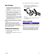
Turn air regulator adjustment knob (F)
counterclockwise until it stops and gauge (E)
reads zero.
E
F
ti21571a
Figure 25
22
332612C


