background image

Repair

Pump

Pump

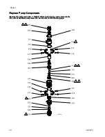
Pump Components

Components

Components Parts

Parts

Parts List

List

List

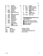
Ref.

Ref.

Ref.

Part

Part

Part

Description

Description

Description

Qty.

Qty.

Qty.

301

301

301

17G220

17G220

17G220

HOUSING,

HOUSING,

HOUSING, outlet

outlet

outlet

1

1

1

302

302

302

17G859

17G859

17G859

NUT,

NUT,

NUT, jam,

jam,

jam, black

black

black

1

1

1

303

303

303

17G865

17G865

17G865

KIT,

KIT,

KIT, bearing,

bearing,

bearing, seal

seal

seal

throat,

throat,

throat, 3–pack

3–pack

3–pack

1

1

1

304

304

304

17G321

17G321

17G321

NUT,

NUT,

NUT, packing,

packing,

packing, 340e

340e

340e

1

1

1

305

305

305

17G331

17G331

17G331

ROD,

ROD,

ROD, short,

short,

short,

displacement

displacement

displacement

1

1

1

306

306

306

17G795

17G795

17G795

GUIDE,

GUIDE,

GUIDE, ball,

ball,

ball, piston

piston

piston

1

1

1

307

307

307

16W491

16W491

16W491

PACKING,

PACKING,

PACKING, cup,

cup,

cup,

3–pack

3–pack

3–pack

1

1

1

308

308

308

17G794

17G794

17G794

VALVE,

VALVE,

VALVE, piston

piston

piston

1

1

1

309

309

309

SEAT,

SEAT,

SEAT, carbide,

carbide,

carbide, valve,

valve,

valve,

piston

piston

piston

1

1

1

310

310

310

PACKING,

PACKING,

PACKING, o

o

o---ring

ring

ring

1

1

1

311

311

311

17G817

17G817

17G817

STOP,

STOP,

STOP, ball,

ball,

ball, piston

piston

piston

1

1

1

312

312

312

17G798†

17G798†

17G798†

BALL,

BALL,

BALL, neoprene,

neoprene,

neoprene, cs

cs

cs

core,

core,

core, 1.625

1.625

1.625

1

1

1

313

313

313

17G330

17G330

17G330

CYLINDER,

CYLINDER,

CYLINDER, short

short

short

1

1

1

314

314

314

PACKING,

PACKING,

PACKING, o

o

o---ring

ring

ring

2

2

2

315

315

315

CLAMP,

CLAMP,

CLAMP, 4

4

4 in.,

in.,

in., 1000

1000

1000

psi

psi

psi

2

2

2

316

316

316

SCREW,

SCREW,

SCREW, cap,

cap,

cap, hex

hex

hex hd

hd

hd

4

4

4

317

317

317

NUT,

NUT,

NUT, extension,

extension,

extension,

3/8–16

3/8–16

3/8–16

4

4

4

Ref.

Ref.

Ref.

Part

Part

Part

Description

Description

Description

Qty.

Qty.

Qty.

318

318

318

17G226

17G226

17G226

HOUSING,

HOUSING,

HOUSING, inlet,

inlet,

inlet, ball

ball

ball

guide

guide

guide

1

1

1

319

319

319

17G221

17G221

17G221

HOUSING,

HOUSING,

HOUSING, inlet

inlet

inlet

1

1

1

320

320

320

SEA,

SEA,

SEA, carbide,

carbide,

carbide, valve,

valve,

valve,

inlet

inlet

inlet

1

1

1

321

321

321

O

O

O---RING,

RING,

RING, 50

50

50 mm

mm

mm xx

x 2.5

2.5

2.5

mm

mm

mm

1

1

1

322

322

322

15H833†

15H833†

15H833†

BALL,

BALL,

BALL, neo/sst

neo/sst

neo/sst core,

core,

core,

1.75

1.75

1.75 in.

in.

in.

1

1

1

323

323

323

17G793

17G793

17G793

GUIDE,

GUIDE,

GUIDE, ball,

ball,

ball, inlet

inlet

inlet

1

1

1

See

See

See List

List

List of

of

of Kits

Kits

Kits table

table

table for

for

for more

more

more information.

information.

information.

1

Apply

Apply

Apply grease

grease

grease lubricant

lubricant

lubricant to

to

to threads,

threads,

threads, oo

o---rings

rings

rings

and

and

and seals.

seals.

seals.

2

Apply

Apply

Apply serviceable

serviceable

serviceable thread

thread

thread locker

locker

locker to

to

to threads.

threads.

threads.

3

Apply

Apply

Apply anti

anti

anti---seize

seize

seize to

to

to threads.

threads.

threads.

4

Torque

Torque

Torque to

to

to 30

30

30 +/

+/

+/---55

5 ftft

ft---lb

lb

lb (40

(40

(40 +/

+/

+/--- 6.7

6.7

6.7 N●m).

N●m).

N●m).

5

Torque

Torque

Torque to

to

to 100

100

100 +/

+/

+/---55

5 ftft

ft---lb

lb

lb (135

(135

(135 +/

+/

+/--- 13.5

13.5

13.5 N●m).

N●m).

N●m).

6

Torque

Torque

Torque to

to

to 200

200

200 +/

+/

+/---55

5 ftft

ft---lb

lb

lb (271

(271

(271 +/

+/

+/--- 13.5

13.5

13.5 N●m).

N●m).

N●m).

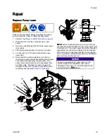
7

Orient

Orient

Orient clamps

clamps

clamps approximately

approximately

approximately as

as

as shown.

shown.

shown.

8

Torque

Torque

Torque to

to

to 10

10

10 +/

+/

+/---22

2 ftft

ft---lb

lb

lb (13

(13

(13 +/

+/

+/--- 2.7

2.7

2.7 N●m).

N●m).

N●m).

List

List

List of

of

of Kits

Kits

Kits

Kit

Kit

Kit

Description

Description

Description

Kit

Kit

Kit Contents

Contents

Contents

25A233

25A233

25A233

Pump

Pump

Pump rebuild

rebuild

rebuild kit

kit

kit

303

303

303 (1),

(1),

(1), 307

307

307 (1),

(1),

(1), 310

310

310 (1),

(1),

(1), 312

312

312 (1),

(1),

(1), 314

314

314 (2),

(2),

(2), 321

321

321 (1),

(1),

(1), 322

322

322 (1)

(1)

(1)

17G456

17G456

17G456

Pump

Pump

Pump lower

lower

lower clamp

clamp

clamp kit

kit

kit

315

315

315 (1),

(1),

(1), 316

316

316 (2),

(2),

(2), 317

317

317 (2)

(2)

(2)

17G862

17G862

17G862

Piston

Piston

Piston seat

seat

seat and

and

and o

o

o---ring

ring

ring

309

309

309 (1),

(1),

(1), 310

310

310 (1)

(1)

(1)

17G863

17G863

17G863

Inlet

Inlet

Inlet seat

seat

seat and

and

and o

o

o---ring

ring

ring

320

320

320 (1),

(1),

(1), 321

321

321 (1)

(1)

(1)

25A467

25A467

25A467

Check

Check

Check ball

ball

ball repair

repair

repair kit

kit

kit

312

312

312 (1),

(1),

(1), 322

322

322 (1)

(1)

(1)

16W490

16W490

16W490

Cylinder

Cylinder

Cylinder o

o

o---ring

ring

ring kit

kit

kit

314

314

314 (10)

(10)

(10)

3A3437F

29

Summary of Contents for ToughTek S340e

Page 1: ...tems EIFS EIFS EIFS For For For professional professional professional use use use only only only Not Not Not approved approved approved for for for use use use in in in explosive explosive explosive atmospheres atmospheres atmospheres or or or hazardous hazardous hazardous locations locations locations Important Important Important Safety Safety Safety Instructions Instructions Instructions Read ...

Page 2: ...ting or Stopping Material Flow 18 Spraying 18 Spray Adjustments Pole Spray Applicator 19 General Adjustments 19 Spraying Techniques 19 Material Flow Adjustment 19 Air Flow Valve Adjustment 19 Installing Nozzle Retaining Cap 19 Spray Adjustments HTXTM Applicator 20 Fluid Drain Purge Valve 21 Pressure Relief Procedure 21 Hopper Removal 22 Shutdown 22 Lifting Instructions 22 Maintenance 23 Daily Main...

Page 3: ...4 25A306 230V 10A 50 60 Hz 1Ф Europe Asia Australia All 230V pumps include a Europe adapter and Australia adapter cord set Related Related Related Manuals Manuals Manuals Manuals are available at www graco com Component manuals in English Manual Manual Manual Description Description Description 3A3438 Pole Spray Applicator 3A3653 HTX Finish Coat Applicator 3A3112 ToughTek F340e Remote Switch Acces...

Page 4: ... oz bottle Lower Lower Lower Assembly Assembly Assembly 25A233 KIT rebuild pump 17G456 KIT lower clamp 16W490 KIT repair 10 pack o ring cylinder end 25A467 KIT repair check balls 17G865 KIT repair 3 pack seal throat triple lip 17G864 KIT pump lower S340e 25A178 KIT conversion F340e to S340e Inlet Inlet Inlet 17G863 KIT repair seat inlet 15H833 BALL neo sst core 1 75 in Piston Piston Piston 17G862 ...

Page 5: ...ket 17J710 KIT F340e adjustable latch 17J708 KIT F340e stop brackets Motor Motor Motor and and and Driver Driver Driver 17J702 KIT F340e MCM 120V 25C512 KIT F340e MCM 120V UK 17J755 KIT F340e MCM 230V 17J711 KIT F340e motor 17J714 KIT F340e finger guard 17J704 KIT F340e front cover 287282 KIT repair shield motor 17J705 KIT F340e tool box 3A3437F 5 ...

Page 6: ...ot lights cigarettes portable electric lamps and plastic drop cloths potential static sparking Ground all equipment in the work area See Grounding Grounding Grounding instructions Keep work area free of debris including solvent rags and gasoline Never spray or flush solvent at high pressure Do not plug or unplug power cords or turn power or light switches on or off when flammable fumes are present...

Page 7: ...uine manufacturer s replacement parts only Do not alter or modify equipment Alterations or modifications may void agency approvals and create safety hazards Make sure all equipment is rated and approved for the environment in which you are using it Use equipment only for its intended purpose Call your distributor for information Route hoses and cables away from traffic areas sharp edges moving par...

Page 8: ...ctions before operating the equipment Check hoses and couplings daily Replace worn or damaged parts immediately TOXIC TOXIC TOXIC FLUID FLUID FLUID OR OR OR FUMES FUMES FUMES HAZARD HAZARD HAZARD Toxic fluids or fumes can cause serious injury or death if splashed in the eyes or on skin inhaled or swallowed Read Safety Data Sheets SDSs to know the specific hazards of the fluids you are using Store ...

Page 9: ...t Component Component Identification Identification Identification Table Table Table Key Key Key A Electric Motor B Pump Lower C Fluid Drain Purge Valve E Remote Pump Control Switch optional F Fluid Outlet H Flow Adjustment Knob J Hopper L Control Board Status Light Key Key Key P Hopper Pin S Motor Power Switch U Hopper Latch 3A3437F 9 ...

Page 10: ... Applicator Applicator Before connecting hoses applicator inspect for damage or wear to both the hose applicator and cam lock fittings Fittings should be clean and free of debris dents cracks or nicks The female cam lock fitting must have the gasket installed Always connect hoses from largest diameter to smallest diameter Use a minimum of 25 ft of hose with a working pressure of at least 600 psi 4...

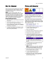
Page 11: ...to the hopper for several cycles before beginning to spray 1 Prime the system with water See Prime with Water page 16 2 Mix the material See Mix the Material page 17 3 Turn the flow adjustment knob H counterclockwise until it stops 4 Remove the applicator 5 Fill the clean hopper with material to be sprayed 6 Place the hose outlet in a waste container 7 Turn the motor power switch S to ON 8 Turn th...

Page 12: ...he plug on the product Make sure your extension cord is not damaged If an extension cord is necessary use 12 AWG 2 5 mm2 minimum to carry the current that the product draws An undersized extension cord results in a drop in line voltage loss of power and overheating NOTE NOTE NOTE Certain GFCI outlets have been known to trip while using this product For 120V units use a dedicated 15 amp circuit Pow...

Page 13: ...ck valve optional Remove fluid outlet assembly F Attach check valve M to pump fluid outlet Attach fluid outlet assembly to check valve M outlet NOTE NOTE NOTE If a check valve M is being used it must be installed between the fluid outlet assembly F and the pump lower to ensure proper operation of the pressure relief valve NOTE NOTE NOTE Check valve M is intended for use with low viscosity fluids s...

Page 14: ...ure page 21 2 Remove applicator tip and retainer 3 Place applicator outlet in a waste container The waste container must be large enough to hold all dispensed material ti21632a 4 Turn motor power switch S on 5 Turn adjustment knob H clockwise slowly to increase pressure until a steady stream flows from gun 6 When the material level in the hopper is within a few inches of the material inlet at the ...

Page 15: ...l is pushed through the hose turn the motor power switch S to OFF Repeat until all sediment is removed from the hose NOTICE NOTICE NOTICE Material left on the throat seal can dry out and damage the seal Always stop the pump at the bottom of the stroke to avoid damage to the throat seal e If using a 1 in whip hose remove the hose and transition fitting and repeat the process using the large clean o...

Page 16: ...tted down before inserting If using a 1 in whip hose begin with the smallest clean out ball c Reattach the hose to the pump outlet and turn the motor power switch S to ON to resume flushing the hose d The clean out ball will be pushed out of the hose after several minutes Once the ball is pushed through the hose turn the motor power switch S to OFF e If using a 1 in whip hose remove the hose and t...

Page 17: ...and requiring replacement of those parts To prevent material curing in system never load material into a dry system The applicator must be removed before priming Always push out any remaining water into a waste container before circulating material Always circulate clean material back into the hopper for several cycles before beginning to spray 1 Prime the system with water See Prime with Water pa...

Page 18: ...NOTICE NOTICE NOTICE Do not allow pump to run without material in the hopper It can cause damage to the pump seals Failure to flush prior to material curing in the system will result in damage to system and may require replacement of all system parts in contact with the material 4 Turn on atomizing air and adjust the air needle valve on the applicator see applicator manual 5 Turn the motor power s...

Page 19: ...regate in the material and the coarseness of the spray pattern Larger nozzles allow heavier patterns 5 Overlap each stroke 50 A circular overlapping pattern may give the best results When spraying small confined areas use the air ball valve CB and air needle CD to make fine adjustments without adjusting the pump Material Material Material Flow Flow Flow Adjustment Adjustment Adjustment For a light...

Page 20: ...ires the correct tip size Air Air Air Flow Flow Flow Valve Valve Valve Adjustment Adjustment Adjustment To decrease air flow turn the valve knob DE clockwise To increase air flow turn the valve knob DE counterclockwise Check material and thin as needed to maintain the proper consistency The material may thicken as it sits and could slow down application or affect the spray pattern Flush and dry th...

Page 21: ...uch as splashing fluid and moving parts follow the Pressure Relief Procedure when you stop spraying and before cleaning checking or servicing the equipment To avoid injury from splashing fluid never open a cam lock hose or applicator fitting while there is pressure in the fluid line 1 Turn the flow adjustment knob H counterclockwise until it stops 2 Turn the motor power switch S off 3 Remove the a...

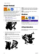
Page 22: ...OTE NOTE If needed push down on the hopper elbow to completely disengage from the pump lower 5 Remove the two hopper pins P from the front legs of the cart 6 Lift up on the handle and pull the hopper J away from the sprayer NOTE NOTE NOTE If the hopper elbow needs to be thoroughly cleaned rotate knob K to loosen the clamp between the elbow and the hopper Remove and clean the elbow NOTE NOTE NOTE T...

Page 23: ...re wear of packings and pump corrosion DAILY DAILY DAILY Check the cam lock connections for damage dings nicks cracks DAILY DAILY DAILY Check the cam lock gasket for damage DAILY DAILY DAILY or or or when when when changing changing changing material material material Break down the pump lower and thoroughly clean and inspect check balls WEEKLY WEEKLY WEEKLY Grease swivel fittings on the applicato...

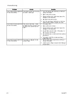
Page 24: ...an or replace tip gun Clamps on hopper elbow are loose Tighten clamps on the hopper elbow Fluid delivery is low Large pressure drop in fluid hose Reduce length or increase diameter Power switch is not ON Turn the power switch ON Electric motor does not operate Tripped circuit breaker Check circuit breaker at power source Reset motor switch Fluid hose or applicator obstructed Clean the hose or appl...

Page 25: ...e problem continues contact your local distributor Control board status light blinks 6 times repeatedly The motor is overheating Allow the sprayer to cool If the sprayer runs when cool correct the cause of overheating Keep the sprayer in a cooler location with good ventilation Make sure the motor air intake is not blocked If the sprayer still does not run contact your local distributor Control boa...

Page 26: ...tatus light blinks 16 times repeatedly Check the connections Check for water in sensor Control is not receiving motor position sensor signal 1 Turn power OFF 2 Remove the motor shroud 3 Disconnect the motor control and inspect for damage at the connectors 4 Inspect the sensor for water If the sensor is wet let it dry for 24 hours 5 Re install the sensor motor control connections and shroud 6 Turn ...

Page 27: ... 6d and assembly coupling 6c The pump lower 6a should now be separated from all other parts Replace the pump lower and reinstall on the unit If pump components need replacing see Replace Pump Components NOTE NOTE NOTE When reinstalling the pump lower the jam nut 19 should be threaded on the pump lower until it bottoms out The pump lower should be threaded completely into the motor adapter 6f and b...

Page 28: ... 17G864 17G864 before before before replacing replacing replacing any any any pump pump pump components components components For For For a a a list list list of of of available available available pump pump pump lower lower lower kits kits kits see see see the the the list list list on on on the the the following following following page page page 28 3A3437F ...

Page 29: ... RING RING RING 50 50 50 mm mm mm x x x 2 5 2 5 2 5 mm mm mm 1 1 1 322 322 322 15H833 15H833 15H833 BALL BALL BALL neo sst neo sst neo sst core core core 1 75 1 75 1 75 in in in 1 1 1 323 323 323 17G793 17G793 17G793 GUIDE GUIDE GUIDE ball ball ball inlet inlet inlet 1 1 1 See See See List List List of of of Kits Kits Kits table table table for for for more more more information information inform...

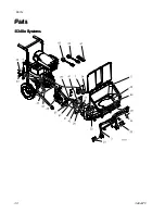
Page 30: ...Parts Parts Parts Parts S340e S340e S340e Systems Systems Systems 30 3A3437F ...

Page 31: ...16 x x x 2 2 2 in in in 4 4 4 29 29 29 100731 100731 100731 WASHER WASHER WASHER 8 8 8 Ref Ref Ref Part Part Part Description Description Description Qty Qty Qty 30 30 30 101566 101566 101566 NUT NUT NUT lock lock lock 4 4 4 34 34 34 SCREW SCREW SCREW cap cap cap hex hex hex hd hd hd 6 6 6 39 39 39 125112 125112 125112 SCREW SCREW SCREW cap cap cap btn btn btn hd hd hd 5 16 5 16 5 16 in in in 4 4 ...

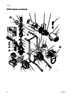
Page 32: ...Parts S340e S340e S340e Systems Systems Systems continued continued continued 32 3A3437F ...

Page 33: ... FITTING FITTING hose hose hose 1 11 1 11 1 11 1 2 1 2 1 2 npt npt npt 1 1 1 50 50 50 127232 127232 127232 VALVE VALVE VALVE ball ball ball 1000 1000 1000 psi psi psi 1 1 1 in in in 1 1 1 51 51 51 128473 128473 128473 FITTING FITTING FITTING 1 5 1 5 1 5 in in in camlock camlock camlock x x x 1 5 1 5 1 5 in in in nptm nptm nptm 2 2 2 52 52 52 GRIP GRIP GRIP vinyl vinyl vinyl gray gray gray 1 25 1 2...

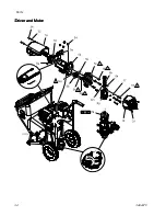
Page 34: ...Parts Driver Driver Driver and and and Motor Motor Motor 34 3A3437F ...

Page 35: ...ocket socket socket head head head 4 4 4 24 24 24 119250 119250 119250 SCREW SCREW SCREW shoulder shoulder shoulder 2 2 2 31 31 31 118444 118444 118444 SCREW SCREW SCREW mach mach mach slot slot slot hex hex hex wash wash wash hd hd hd 4 4 4 32 32 32 276980 276980 276980 GROMMET GROMMET GROMMET cover cover cover 2 2 2 34 34 34 SCREW SCREW SCREW cap cap cap hex hex hex hd hd hd 6 6 6 76 76 76 19284...

Page 36: ...ntrol control elec elec elec std std std 1 1 1 217 217 217 16T784 16T784 16T784 LABEL LABEL LABEL warning warning warning EN FR ES EN FR ES EN FR ES 1 1 1 218 218 218 16U215 16U215 16U215 SCREW SCREW SCREW phillips phillips phillips pan pan pan hd hd hd plastite plastite plastite 1 1 1 219 219 219 114391 114391 114391 SCREW SCREW SCREW grounding grounding grounding 1 1 1 220 220 220 LABEL LABEL LA...

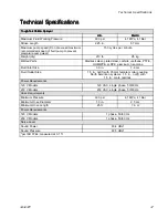
Page 37: ...Stainless steel plated steel carbide urethane PTFE UHMWPE LLDPE aluminum neoprene Fluid inlet Size 3 0 in 7 6 cm Fluid Outlet Size 1 5 in npt f with 35 mm female mortar coupling North American systems 1 5 in npt f with 1 5 in male camlock Power Requirements 120 V Models 120 VAC single phase 50 60 Hz 230 V Models 230 VAC single phase 50 60 Hz Hose Requirements Minimum Pressure 600 psi 4 1 MPa 41 Ba...

Page 38: ... WARRANTY WARRANTY AND AND AND DISCLAIMS DISCLAIMS DISCLAIMS ALL ALL ALL IMPLIED IMPLIED IMPLIED WARRANTIES WARRANTIES WARRANTIES OF OF OF MERCHANTABILITY MERCHANTABILITY MERCHANTABILITY AND AND AND FITNESS FITNESS FITNESS FOR FOR FOR A A A PARTICULAR PARTICULAR PARTICULAR PURPOSE PURPOSE PURPOSE IN IN IN CONNECTION CONNECTION CONNECTION WITH WITH WITH ACCESSORIES ACCESSORIES ACCESSORIES EQUIPMENT...

Reviews: