background image

Common Procedures 

20

334179B

Common Procedures

Installing Spray Tips

Two spray tips are available for use with this
sprayer. The black tip produces a 12-inch
wide spray pattern. The gray tip produces a
4-inch wide spray pattern.
Either spray tip may be used to spray
materials that are recommended to be
strayed with a 0.015 tip size. See material
container for spray tip size
recommendations.

Remove Spray Tip

1.

Perform 

Pressure Relief Procedure

page 16

.

2.

Rotate the spray tip 90 degrees from 
either the SPRAY or UNCLOG position.

3.

Pull the spray tip straight out of the spray 
tip guard.

Install Spray Tip

1.

While holding the spray tip 90 degrees 
from either the SPRAY or UNCLOG 
position, align spray tip locking tab with 
the locking tab slot in the spray tip guard.

2.

Push the spray tip all the way into the 
spray tip guard.

3.

Rotate the spray tip to the SPRAY 
position.

NOTE: 

Make certain spray tip locking tab is 

pushed all the way into the slot in the spray tip 
guard. You should not be able to remove the 
spray tip from the spray tip guard when it is in 
the Spray or Unclog positions.

NOTE: 

If the locking tab slot in the spray tip 

guard is blocked, preventing installation of 
the spray tip, rotate the spray tip guard until it 
is visually aligned with the internal hole, then 
install the spray tip.

Spray tips wear with use and abrasive 
paint and need periodic replacement.

If the spray pattern is poor, you may have 
a worn spray tip. Replace spray tip. See 

Spray Pattern Diagnostics

, page 30.

Do not put your hand in front of the spray 
tip.

ti23563a

LOCKING TAB SLOT

LOCKING 

REMOVE
SPRAY TIP

TAB

ROTATE
SPRAY TIP

NOTICE

The spray tip guard is permanently 
attached to the sprayer. Removal for 
cleaning is not necessary and will result in 
damage to the sprayer.

NOTICE

Spray tips must be cleaned or stored in 
appropriate cleaning fluid (water or Pump 
Armor) immediately after use to ensure 
material is not allowed to dry in spray tip. 
Failure to do so will result in damage to the 
spray tip. See 

Cleanup

, page 16.

Summary of Contents for TrueCoat 360 16Y391

Page 1: ...s manual and on the unit including the power cord Be familiar with the controls and the proper usage of the equipment Save these instructions ti24623a Scan QR code or click on link for operational video http graco com tc360opvid Owners Manual Project Series Paint Sprayers WARNING Use only water based materials Do not use materials which state FLAMMABLE on the packaging For more information about y...

Page 2: ...orage 19 Common Procedures 20 Installing Spray Tips 20 Unclogging Spray Tip 21 Flushing a New Sprayer 22 Replacement Parts 24 Models 16Y391 16Y392 24 Parts List Models 16Y391 16Y392 25 Replacement Parts 26 Model 17F329 26 Parts List Model 17F329 27 Troubleshooting 28 Technical Data 32 Graco Limited Warranty 33 Model Name Voltage Tip Size Description Maximum Working Pressure 16Y391 TrueCoat 360 230...

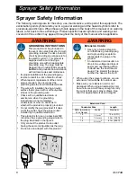
Page 3: ...th your sprayer Ask for a Safety Data Sheet SDS from your supplier The container label and SDS will explain the contents of the material and the specific precautions related to it Paints coatings and clean up materials generally fit into one of the following 2 basic categories WATER BASED The container label should indicate that the material can be cleaned up with soap and water Your sprayer is co...

Page 4: ...oors use an extension cord suitable for outdoor use Use of a cord suitable for outdoor use reduces the risk of electric shock If operating a power tool in a damp location is unavoidable use a residual current device RCD protected supply Use of an RCD reduces the risk of electric shock Personal Safety Stay alert watch what you are doing andusecommonsensewhenoperating a power tool Do not use a power...

Page 5: ...nd do not allow persons unfamiliar with the power tool or these instructions to operate the power tool Power tools are dangerous in the hands of untrained users Maintain power tools Check for misalignment or binding of moving parts breakage of parts and any other condition that may affect the power tool s operation If damaged have the power tool repaired before use Many accidents are caused by poo...

Page 6: ...having an outer surface that is green with or without yellow stripes is the grounding wire Check with a qualified electrician or serviceman when the grounding instructions are not completely understood or when in doubt as to whether the product is properly grounded Do not modify the plug provided if it does not fit the outlet have the proper outlet installed by a qualified electrician This product...

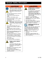
Page 7: ... Sheets SDS and container labels provided with the paints and solvents Follow the paint and solvents manufacturer s safety instructions Fire extinguisher equipment shall be present and working WARNING SKIN INJECTION HAZARD High pressure spray is able to inject toxins into the body and cause serious bodily injury In the event that injection occurs get immediate surgical treatment Do not aim the spr...

Page 8: ... FUMES HAZARD Toxic fluids or fumes can cause serious injury or death if splashed in the eyes or on skin inhaled or swallowed Read SDS s to know the specific hazards of the fluids you are using Store hazardous fluid in approved containers and dispose of it according to applicable guidelines WARNING PRESSURIZED ALUMINUM PARTS HAZARD Use of fluids that are incompatible with aluminum in pressurized e...

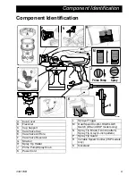
Page 9: ...p Support D VacuValve Cap E VacuValve Air Hole F VacuValve Reservoir G Strainer H Spray Tip Holder J Prime Pump Spray Knob K Power Cord L Sprayer Trigger M Dual Speed Control HIGH LOW Switch DS and DSP models only N Spray Tip Black 12 inch pattern Spray Tip Gray 4 inch pattern P Spray Tip Guard R Variable Speed Control VSP models only S Kickstand ...

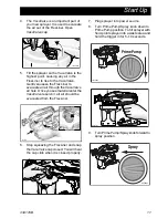
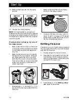
Page 10: ...e arrow on the cup cover is within range of the indicator on the cup support 3 Align VacuValve on cup cover with Prime Pump Spray knob Push cup assembly onto sprayer and twist clockwise to lock Use only water based materials Do not use materials which state FLAMMABLE on the packaging For more information about your material request SDS from distributor or retailer Keep spray area well ventilated K...

Page 11: ...hole Once you see material enter the VacuValve reservoir all air should be evacuated from the FlexLiner 6 Stop squeezing the FlexLiner and snap the VacuValve cap closed You will hear the cap click when it is closed properly 7 Plug sprayer into power source 8 Turn Prime Pump Spray knob down to Prime Pump position To fill sprayer with fluid point sprayer into a waste area and hold the trigger in for...

Page 12: ...readed Fully remove the cup cover and reinstall to the cup support so no threads are visible when tight Repeat steps 2 6 on pages 10 11 to ensure all the air is evacuated from the FlexLiner Make certain the Prime Pump Spray knob is in the Spray position If sprayer still does not spray perform steps 10 and 11 on page 23 If material sprays while upside down there is air in the cup Repeat steps above...

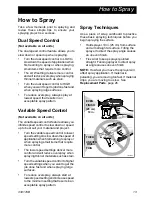
Page 13: ...trol to lower speedsettingstoslowdownthe speed of applicationwhenfirstlearningtosprayor when spraying small items that require more control The lower speed settings deliver more control and will reduce overspray when spraying thinner materials such as stain Turn the variable speed control to higher speed settings when you want to get the job done fast and when spraying large surfaces To reduce ove...

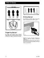
Page 14: ...released Aiming Sprayer Aim sprayer at bottom edge of previous stroke overlapping each stroke by half Rotating the spray tip guard changes the pattern to either the vertical or horizontal orientations When spraying vertical corners turn spray tip guard to the horizontal orientation and move sprayer up and down ti23375a EVEN FINISH THICK THIN THIN ti23376a ti23378a ...

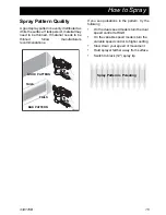
Page 15: ...w manufacturers recommendations If you see pulsations in the pattern try the following On the dual speed models turn the dual speed control to HIGH On the variable speed models turn the variable speed control to higher setting Slow down your speed of movement Hold sprayer farther away from surface Switch to black 12 spray tip ti23382a GOOD PATTERN BAD PATTERN TAILS TAILS Spray Pattern is Pulsating...

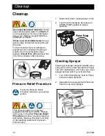
Page 16: ...he cup cover sprayer Use only water based materials Do not use materials which state FLAMMABLE on the packaging For more information about your material request SDS from distributor or retailer Clean in a well ventilated area Keep a good supply of fresh air moving through the area To avoid serious injury or damage to equipment do not expose the sprayer electronics to cleaning fluids Keep sprayer a...

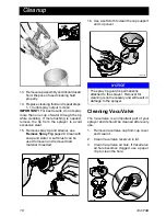
Page 17: ... certain the Prime Pump Spray knob is in the Prime Pump position pointed down On models with a dual speed control switch set speed control to HIGH On variable speed models set speed control to 10 9 Turn the sprayer upside down and point the sprayer into a waste pail Pull the trigger for ten seconds 10 Turn Prime Pump Spray knob forward to SPRAY position Reverse spray tip to UNCLOG position 11 Whil...

Page 18: ... with soap and water A soft brush can be used to loosen and remove dried material if needed 16 Use a soft cloth to clean the cup support and cup cover Cleaning VacuValve The VacuValve is an important part of your sprayer and it should be cleaned after every use 1 Remove VacuValve cap from cup cover and clean it 2 Clean VacuValve reservoir in lid 3 Clean VacuValve air hole If VacuValve air hole bec...

Page 19: ... Install strainer into pump opening 7 With sprayer upside down attach cup support with FlexLiner to sprayer 8 Holding sprayer upside down over a waste container pull sprayer trigger for three seconds 9 Turn Prime Pump Spray knob forward to spray position Remove cup assembly and pour any remaining Pump Armour back into Pump Armor bottle Replace child resistant cap and tighten securely for storage 1...

Page 20: ...locking tab is pushed all the way into the slot in the spray tip guard You should not be able to remove the spray tip from the spray tip guard when it is in the Spray or Unclog positions NOTE If the locking tab slot in the spray tip guard is blocked preventing installation of the spray tip rotate the spray tip guard until it is visually aligned with the internal hole then install the spray tip Spr...

Page 21: ... 4 Dual speed models Move speed control switch to HIGH setting 5 Variable speed models Set speed control to 10 6 Aim sprayer at waste area turn Prime Pump Spray knob forward to spray position Pull trigger to clear clog 7 Turn Prime Pump Spray knob down to Prime position Rotate spray tip back to SPRAY position Turn Prime Pump Spray knob forward to SPRAY position and resume spraying 8 If spray tip i...

Page 22: ... using it for the first time 1 Remove cup assembly from the sprayer by turning counter clockwise and pulling down 2 Unscrew cup cover from the cup support 3 Make certain FlexLiner is in the cup support 4 Fill FlexLiner with water 5 Securely tighten cup cover onto cup support Tighten so the arrow on the cup cover is within range of the indicator on the cup support ti23249b ti23676a ti23361a ti23383...

Page 23: ...Pump Spray knob forward to SPRAY position Rotate spray tip 180 degrees to UNCLOG position 11 While holding the sprayer upside down point the sprayer into a waste pail Pull the trigger for three seconds IMPORTANT For best results do not spray more than one cup of water through the tip while cleaning If more flushing is needed remove the tip from the sprayer to avoid excessive wear 12 Sprayer is now...

Page 24: ...Replacement Parts 24 334179B Replacement Parts Models 16Y391 16Y392 8 19 19 20 13b 12 7 8 5 1 10 2 6 3 4 9 18 17 16 14 15 13a 22 24 ti24627a ti23568a 26 ...

Page 25: ...l electronic includes motor power cord and switch 16Y391 17B913 Single speed 230 V not shown 16Y392 17B914 Dual speed 230 V 13a 16Y392 16X868 Switch dual speed control 13b 16Y391 16X869 Plug 14 All models 16W846 Support cup 15 All models 17A226 Kit FlexLiner 3 pack 16 All models 17B636 Cover cup 17 All models 115719 O ring 18 All models 16X806 VacuValve cap 19 16Y391 17A227 Kit enclosure blue incl...

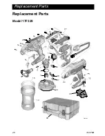
Page 26: ...Replacement Parts 26 334179B Replacement Parts Model 17F329 8 20 24 13 8 5 1 10 2 6 3 4 18 17 16 4 15 22 2 28 26 27 ti26108a ...

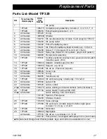
Page 27: ...d switch Variable speed 230 V 13 17F329 17D844 Adapter variable speed control 14 17F329 17D850 Support cup 42 oz 15 17F329 17F005 Kit 42 oz FlexLiner 3 pack 16 All models 17B636 Cover cup 17 All models 115719 O ring 18 All models 16X806 VacuValve cap 19 17F329 17A649 Kit enclosure gray includes qty 13 of ref 8 20 All models 16Y680 Label USA 22 All models 16Y678 Label control 23 All models 17A470 L...

Page 28: ...pport Make certain the cup cover is properly threaded to the cup support If threads are visible below the cup cover when tight fully remove and reinstall to the cup support so no threads are visible when tight Make certain the cup cover is tightened to cup support so the arrow on cup cover is within range of indicator on cup support Make certain the cup assembly is properly locked on the sprayer M...

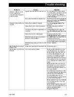
Page 29: ... manufacturer srecommendation for the material being sprayed Material being sprayed is too cold to spray Warm material Paint leaks from sprayer trigger area Pump has reached its maximum life Replace pump Paint leaks out of the cup threads Cup not properly seated Make certain that there is only one FlexLiner in cup support Make certain the cup cover is properly threaded to the cup support If thread...

Page 30: ...d pattern is achieved Material may need to be thinned Thin material follow paint manufacturer s recommendations Incorrect spray tip for application of material Install different size spray tip See Installing Spray Tips page 20 Material not compatible with sprayer Switch material Spray tip is worn or damaged Replace spray tip See Installing Spray Tips page 20 Spray pattern has dripping sagging Oper...

Page 31: ...ge 20 Spray pattern spits at the end or beginning Excess material has accumulated on spray tip guard assembly or spray tip is partially clogged Clean spray tip guard See Unclogging Spray Tip page 21 Spray tip not inserted completely into spray tip guard See Installing Spray Tips page 20 Spray tip is worn Replace spray tip See Installing Spray Tips page 20 Spray tip continues to drip or ooze materi...

Page 32: ...y K 3 dB A Sound Power Level Per ISO 3744 86 8 dB A uncertainty K 3 dB A Vibration Level Measured in accordance with EN60745 1 3 41 ft s2 uncertainty k 4 9 ft s2 1 04 m s2 uncertainty K 1 5 m s2 Power Cord 18 AWG 3 wire 18 in 2 1 0 mm2 3 wire 45 cm Electrical Power Requirement 220 240Vac 50 Hz 10A 1 phase Duty Cycle 50 Maximum tip orifice 0 015 in 0 38mm Pump damage will occur if fluid freezes in ...

Page 33: ... or workmanship repairs will be made at a reasonable charge to you which charges may include the costs of parts labor and transportation Repair or replacement of the product under this warranty will not interrupt or extend the warranty period or create a new warranty period ANY IMPLIED WARRANTY OF MERCHANTABILITY OR FITNESS FOR A PARTICULAR PURPOSES IS LIMITED TO ONE 1 YEAR FROM THE DATE OF PURCHA...

Page 34: ...changes at any time without notice Original instructions This manual contains English MM 334179 Graco Headquarters Minneapolis International Offices Belgium China Japan Korea GRACO INC AND SUBSIDIARIES P O BOX 1441 MINNEAPOLIS MN 55440 1441 USA Copyright 2014 Graco Inc All Graco manufacturing locations are registered to ISO 9001 www graco com Revision B April 2015 ...

Reviews: