
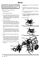
Motor Brush
NOTE:
Replace brushes when worn to about 0.4 in.
(10 mm). Always check both brushes. Brush Repair Kit
235–727 is available.
NOTE:
Replacement brushes may last only half as
long as the original ones. To maximize brush life,
break in new brushes by operating the sprayer with no
load (remove the pump connecting rod pin) for at least
1 hour.
WARNING
To reduce the risk of serious injury, follow the
Pres-
sure Relief Procedure Warning
on page 21 be-
fore doing this procedure. Unplug the sprayer!
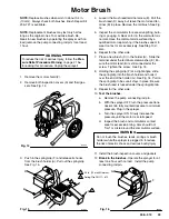
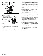
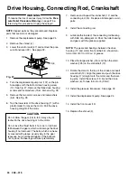
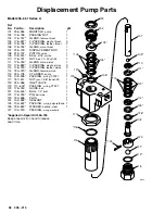
1. Remove the motor shield (2).
2. Remove both inspection covers (A) and their gas-
kets. See Fig. 14.
Fig. 14
02992
A
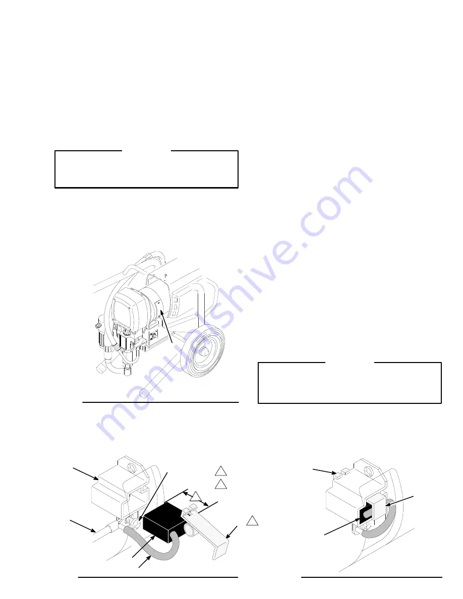
3. Push in the spring/clip (F) and release its hooks
from the brush holder (A). Pull out the spring/clip.
See Fig. 15.
4.
Loosen the brush lead terminal screw (E). Pull the
brush lead (D) away, but leave the motor lead ter-
minal (B) in place. Remove the old brush. See Fig.
15.
5. Inspect the commutator for excessive pitting, burn-
ing or gouging. A black color on the commutator is
normal. Have the commutator resurfaced by a
qualified motor repair shop if the brushes seem to
wear too fast or arc excessively. See Step 10.d..
also.
6. Repeat for the other side.
7. Place a new brush (C) in the holder (A). Slide the
terminal under the terminal screw washer (E). En-
sure the motor lead (B) is still connected at the
screw. Tighten the screw. See Fig. 15.
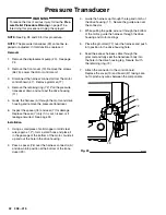
8. Holding the spring/clip (F) at a slight angle, slide
the spring/clip into the brush holder and hook it
over the end of the holder (G). See Fig. 16. Pull on
the spring/clip to be sure it stays in place. Be sure
the brush lead is tucked under the spring/clip tab.
9. Repeat for the other side.
10.
Test the brushes.
a. Remove the pump connecting rod pin.
b. With the sprayer OFF, turn the pressure trans-
ducer knob fully counterclockwise to minimum
pressure. Plug in the sprayer.
c. Turn the sprayer ON. Slowly increase the
pressure until the motor is at full speed.
d. Inspect the brush and commutator contact
area for excessive arcing. Arcs should not
“trail” or circle around the commutator surface.
WARNING
Do not touch the brushes, leads, springs or brush
holders while the sprayer is plugged in to reduce
the risk of electric shock and serious bodily injury.
11. Install the brush inspection covers and gaskets.
12.
Break in the brushes.
Operate the sprayer for at
least one hour with no load. Install the pump
connecting rod pin.
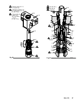
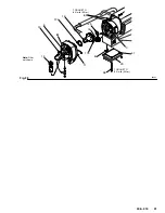
Fig. 15
Fig. 16
0.4 in. (10 mm) Minimum
A
B
C
D
E
F
C
F
G
Spring/Clip P.N.111–610
01065
01066