


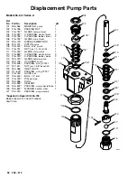
Displacement Pump
WARNING
To reduce the risk of serious injury, follow the
Pres-
sure Relief Procedure Warning
on page 21 be-
fore doing this procedure. Unplug the sprayer!
NOTE:
Packing Repair Kit 235–703 is available. Refer-
ence numbers of parts included in the kit are marked
with an asterisk, i.e., (121*). For the best results, use
all the new parts in the kit, even if the old ones still look
good.
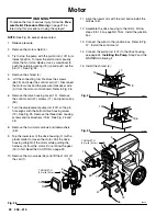
NOTE:
To minimize down time, and for the best spray-
er performance, check the motor brushes (see page
23) and clean the transducer (see page 32) whenever
you repack the pump. Replace these parts as needed.
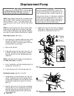
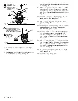
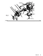
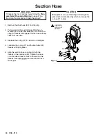
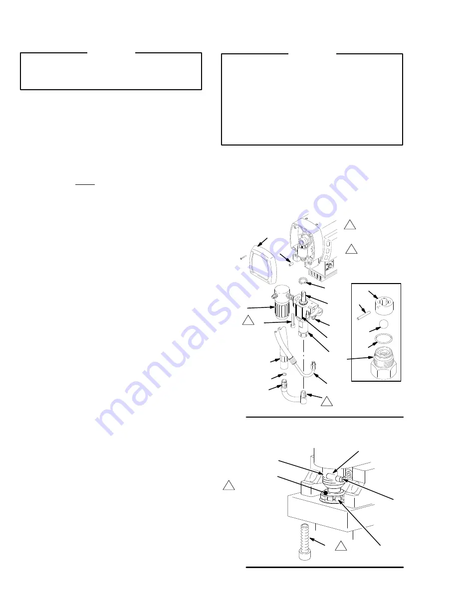
Removing the pump
(See Fig.17)
1. Flush the pump, if possible. Relieve pressure. Stop
the pump with the piston rod (107) in its lowest
position, if possible. To lower the piston rod manu-
ally, rotate the motor fan blades.
2. Remove the filter (85).
3. While pulling upward on the suction hose (32), un-
screw the hose from the inlet tube (38). Unscrew
the drain hose (33) from the displacement pump
nipple (36).
NOTE:
If repairing only the intake valve assembly, go
to
Intake valve repair,
on page 25.
4. Use a screwdriver to push the retaining spring (18)
up and push out the pin (17).
5. Loosen the screws (21). Remove the pump (20).
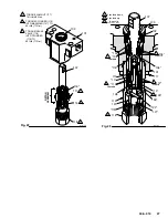
Installing the pump
(See Fig. 17 and 18)
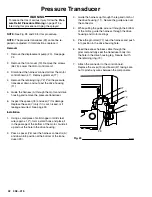
1. Lightly grease or oil the transducer (29). See Fig-
ure XX. Guide the pump over the alignment pins
and pressure transducer. Tap it into position with a
soft hammer. Tighten the screws (21) to 50 ft-lb
(68 N.m).
2. Align the hole in the rod (107) with the connecting
rod assembly (15). Use a screwdriver to push the
retaining spring (18) up and push in the pin (17).
Push the retaining spring (18) into place around
the connecting rod.
WARNING
Be sure the retaining spring (18) is firmly in the
groove all the way around, to prevent the pin (17)
from working loose due to vibration.
See Fig. 18.
If the pin works loose, it or other parts could break
off due to the force of the pump action. These
parts could be projected into the air and result in
serious injury or property damage, including the
pump connecting rod or bearing housing.
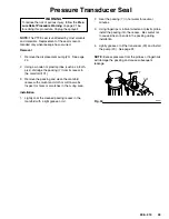
3. Replace the o-ring (27) if it is worn or damaged.
See page 34. Reconnect the suction and drain
hoses (32,33). Install the front cover (13).
118
*119
*121
*122
120
107
18
17
21
20
33
32
36
38
27
13
Fig. 17
TORQUE TO
50 ft–lb
(68 N.m)
02993
Apply pipe
sealant (42e)
85
17
18
123
15
Fig. 18
21
102
TORQUE TO
50 ft–lb (68 N.m)
01068


