


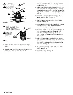
4. Tighten the packing nut (102) just enough to stop
leakage, but no tighter. Fill the packing nut/wet-cup
1/3 full with Graco TSL. Push the plug (123) into
the wet-cup.
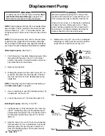
Intake valve repair
(See Fig. 17)
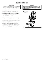
1. Remove the suction hose. See Step 3,
Removing
the pump.
2. Unscrew the intake valve (118). Remove the
o-ring (119*), ball guide (120), stop pin (122*) and
ball (121*) from the valve.
3. Clean and inspect the parts for wear or damage.
Replace parts as needed. Use a new o–ring
(119*). If no further service is needed, reassemble
the pump.
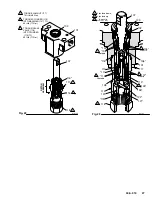
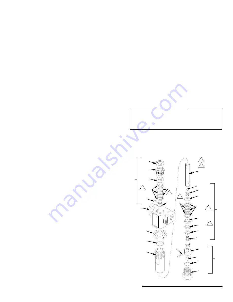
Disassembling the pump
(See Fig. 19)
1. Remove the intake valve (118).
2. Loosen the packing nut (102) and plug (123).
3. Use a plastic mallet to tap the piston rod (107)
down, and then pull the rod out through the bottom
of the cylinder.
4. Remove the packing nut (102) and throat
packings.
5. Loosen the jam nut (117). Remove the cylinder
(115) and the o-ring (116*).
6. Clamp the flats of the piston rod in a smooth jaw
vise. Use an open-end wrench to loosen the nut
(110) and then unscrew the piston valve (108).
7. Remove all parts from the piston valve (108).
Reassembling the pump
NOTE:
Alternate plastic and leather packings. See Fig.
19. The lips of the throat V-packings face down. The
lips of the piston V–packings face up. The lips of seal
125* face down. Incorrect installation damages the
packings and causes pump leaks.
NOTE:
Soak the leather packings in oil before reas-
sembling the pump.
1. Check the outside of the piston rod (107) and the
inside of the cylinder (115) for wear. Replace worn
parts to ensure a good seal with the new packings.
2. Stack these parts onto the piston valve (108) one
at a time: the backup washer (126*) and u–cup
(125*), the female gland (114*), alternately three
plastic (112*) with two leather packings (113*),
and the male gland (111*). See Fig. 20.
3. Tighten the nut (110) onto the piston valve (108) to
2 in-lb (0.23 N.m). See Fig. 21.
Note the alignment
of the piston (108) to the nut
(110). Maintain this alignment through Step 8.
4. Clean all residue from the piston valve threads.
Apply one drop of adhesive, supplied, to the
threads.
5. Place the ball (109*) on the piston valve (108). See
Fig. 20.
CAUTION
Step 8, tightening the piston valve into the rod, is
critical. Follow the procedure carefully to avoid
damaging the packings by overtightening.
6. Hand tighten the valve into the piston rod just until
the nut (110) contacts the rod. See Fig. 21.
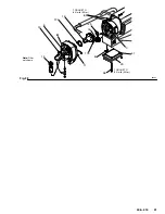
107
109*
110
111
112*
114*
108
123
102
*103
*104
105*
*106
101
117
*116
115
*113
118
Fig. 19
*119
*121
120
*122
125*
126*
127
Lips down.
Lips up.
03149


