background image


Motor

WARNING

To reduce the risk of serious injury, follow the 

Pres-

sure Relief Procedure Warning 

on page 21 be-

fore doing this procedure. Unplug the sprayer!

NOTE: 

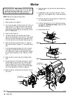
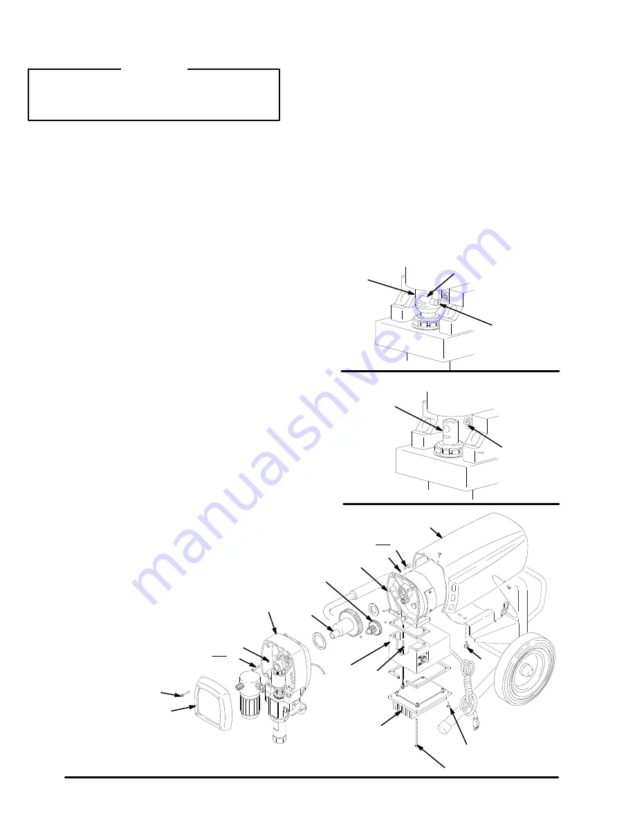
See Fig. 26 except where noted.

1. Relieve pressure.

2. Remove the motor shield (4).

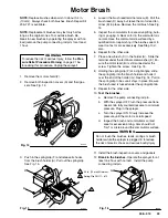
3. Try to stop the pump with the piston rod (107) in its

lowest position. To lower the piston rod manually,
rotate the motor fan blades. Use a screwdriver to
push the retaining spring (18) up and push out the
pin (17). See Fig. 24.

4. Remove the shroud (4).
5.  Lift the connecting rod.  Remove the screws

(56,75) and lower the control card (47). Disconnect
the motor wires and the pressure transducer wire
(A) from the motor control board. Refer to Fig. 26.

6. Remove the drive housing cover (13).  Remove

the control card (47), screws (71), and junction box
(59).

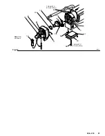
7. Turn the displacement pump rod (107) so the pin

hole aligns with the bottom drive housing screw
(19). See Fig. 25. Remove the three drive housing
screws and lockwashers (19,6).  See Fig. 25 and
26

.

8. Remove the two motor screws and lockwashers

(5,6).

9. Tap the lower rear of the drive housing (11) with a

plastic mallet to loosen the motor. Pull the drive
housing straight off the motor while guiding the
harness (A) from the motor. Do not allow the gear
(16) to fall. Read the CAUTION on page 30.

10. Remove the two screws (46) and lift the motor off

the cart (1).

11. Align the new motor with the cart and reinstall the

screws (46).

12. Assemble the drive housing to the motor. Follow

steps 8 to 14 on page NO TAG.  Install the junction
box.

13. Connect the wires in the junction box. Refer to Fig.

12.  Install the control card.

14. Connect the piston rod (107) to the drive housing;

see page 24, 

Installing the Pump

, Step 2 and the

WARNING following it.

15. Install the shroud (4).

17

18

15

Fig. 24

01068

107

19,6

Fig. 25

01074

19

6

13

34

59

56

12

16

11

4

5

6

46

TORQUE TO

80 in–lb (9 N.m)

TORQUE TO

80 in–lb (9 N.m)

Fig. 26

A

02994

75

47

71

Summary of Contents for ULTRA 600 231-307 Series A

Page 1: ...hout a tip guard In case of accidental skin injection seek immediate Surgical Treatment Failure to follow this warning can result in amputation or serious injury FIRE AND EXPLOSION HAZARD SKIN INJECTION HAZARD READ AND UNDERSTAND ALL LABELS AND INSTRUCTION MANUALS BEFORE USE Spray painting flushing or cleaning equipment with flammable liq uids in confined areas can result in fire or explosion Use ...

Page 2: ... 23 Displacement Pump 24 Motor 28 Motor Control Board 29 Power Supply Cord 29 On Off Switch 29 Drive Housing Connecting Rod Crankshaft 30 Pressure Transducer 32 Pressure Transducer Seal 33 Suction Hose 34 Drain Valve 35 Complete Sprayer Parts 36 Displacement Pump Parts 38 Dimensions 39 Accessories 39 Graco Ultra Warranty and Disclaimers 40 Phone Numbers 40 ...

Page 3: ...k of fluid injection when the tip is not installed Check diffuser operation regularly Follow the Pressure Relief Procedure below then remove the spray tip Aim the gun into a metal pail hold ing the gun firmly to the pail Using the lowest possible pres sure trigger the gun If the fluid emitted is not diffused into an irregular stream replace the diffuser immediately Tip Guard ALWAYS have the tip gu...

Page 4: ...a tures above 180 F 82 C or below 40 F 40 C Hose Grounding Continuity Proper hose grounding continuity is essential to maintaining a grounded spray system Check the electrical resistance of your fluid hoses at least once a week If your hose does not have a tag on it which specifies the maximum electrical resis tance contact the hose supplier or manufacturer for the maxi mum resistance limits Use a...

Page 5: ...lement Diffuser Le diffuseur du pistolet sert à diviser le jet et à réduire les risques d injection accidentelle quand l ajutage n est pas en place Vérifier le fonctionnement du dif fuseur régulièrement Pour cette vérification détendre la pression en observant la Marche à Suivre pour Détendre la Pression donnée plus loin puis en lever l ajutage du pulvérisateur Pointer le pistolet dans un seau en ...

Page 6: ...ise à la terre ou avec une mise à la terre incorrecte peut en traîner des risques pour votre systeme Lisez aussi LES RISQUES D INCENDIE OU D EXPLOSIÓN ci dessus RISQUES D INCENDIE OU D EXPLOSION De l électricité statique est produite par le passage du fluide à grande vitesse dans la pompe et dans les tuyaux Si toutes les pièces de l appareil de pulvérisation ne sont pas convenable ment reliés à la...

Page 7: ...o imprevisto de la pistola Difusor El difusor de la pistola dispersa el chorro pulverizado y reduce el riesgo de inyección cuando no está instalada la boquilla Revisar con regularidad el funciónamiento del difusor Seguir el procedimiento de descarga de presión dado más abajo y después sacar la boquilla Apuntar la pistola a un balde metáli co sosteniéndola bien firme contra el Utilizando la presión...

Page 8: ...sar un metro de resistencia en la gama apropiade para comprobar la resistencia si excede los límites recomendados reemplazarla de inmediato Es muy ar riesgado tener una manguera sin puestá a tierra o con la puestá a tierra en malas condiciónes Leer también la información sobre RIESGO DE INCENDIO O EXPLOSION más arriba PELIGRO DE INCENDIO O EXPLOSION El flujo a alta velocidad del fluido al pasar po...

Page 9: ...n t use thread sealant and don t install the spray tip yet 2 Fill the wet cup D Pry off the wet cup seal Fill the cup 1 3 full with Graco Throat Seal Liquid TSL 68 supplied Install the seal 3 Check the electrical service Be sure it is 120 V 60 HzAC 15 Amp minimum Use a properly grounded outlet Do not remove the third ground ing prong of the power supply cord and do not use an adapter Use a 3 wire ...

Page 10: ...ow to use the pressure drain valve Use the pressure drain valve to relieve fluid pressure from the pump and to help prime the pump If the valve senses an over pressure condition it opens automati cally to relieve fluid pressure If this happens stop spraying immediately shut off and unplug the sprayer Determine the cause of the problem and correct it be fore operating the sprayer again Refer also t...

Page 11: ... spray gun with the tip guard removed DO NOT hold your hand body or a rag in front of the spray tip when cleaning or checking a clogged tip Always point the gun toward the ground or into a pail when checking to see if the tip is clear DO NOT try to blow back paint this is NOT an air spray sprayer The tip guard alerts you to the risk and helps prevent placing any part of the body close to the spray...

Page 12: ...he suction hose C into the paint If you are pumping from a 1 gallon 5 liter pail push the drain hose D down below the top of the pail to avoid splashing paint when the drain valve is opened 4 Turn the pressure knob E to the minimum setting 5 Disengage the gun safety latch See Fig 2 page 10 CAUTION To reduce the risk of damage to the displacement pump packings never run the pump without fluid in it...

Page 13: ...e manual 307 848 for how to install the tip 10 Adjust the spray pattern a Increase the pressure just until spray from the gun is completely atomized To avoid exces sive overspray and fogging and to extend tip and sprayer life always use the lowest pres sure needed to get the desired results b If more coverage is needed use a larger tip rather than increasing the pressure c Test the spray pattern T...

Page 14: ... 100 hours of operation Remove the front cover Apply several drops of SAE 10 non detergent oil in the bearing housing cavity B See Fig 9 5 Flush the sprayer at the end of each work day and fill it with mineral spirits to help prevent pump corrosion and freezing See page 15 CAUTION To prevent pump corrosion and to reduce the chance of fluid freezing in the pump in cold weather never leave water or ...

Page 15: ... spirits Mineral spirits Mineral spirits Change oil to latex paint Mineral spirits soapy water and clean water Latex Warm soapy water then clean water Mineral spirits Change colors same base Compatible solvent such as water or mineral spirits How to flush 1 Follow Pressure Relief Procedure See page 11 2 Remove the spray tip and clean it separately If you are changing from water based to oil based ...

Page 16: ...solvent to thoroughly clean the sprayer Release the gun trigger Engage the gun safety latch 8 Open the drain valve and circulate the solvent through the drain hose to thoroughly clean it Close the drain valve 9 Remove the suction hose from the pail Disengage the gun safety latch Trigger the gun and run the pump a few seconds to push air into the hose Do not run the pump dry for more than 30 second...

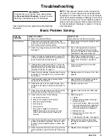
Page 17: ...etely pushed into connecting rod 15 and retaining spring 18 must be firmly in connecting rod groove See Fig 18 page 24 2 Push pin into place and secure with spring retainer 3 Check for motor damage Remove drive housing assembly 11 See page 30 Try to rotate motor fan by hand 3 Replace motor 4 if fan won t turn See page 28 Electrical 1 Check electrical supply with volt meter Meter should read 105 12...

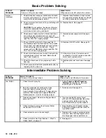
Page 18: ...hm maximum 11 Allow motor to cool Correct cause of overheating If switch remains open after motor cools replace motor 12 Check the transducer 29 by replacing it with a new one 12 Replace pressure transducer See page 32 13 Check pressure adjustment potentiometer 64 by replacing it with a new one Intermediate Problem Solving TYPE OF PROBLEM WHAT TO CHECK If check is OK go to next check WHAT TO DO Wh...

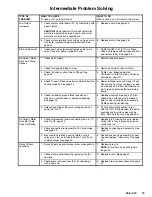
Page 19: ... ed See page 24 Strain paint before us ing to remove particles that could clog pump 5 Check for leaking around throat packing nut which may indicate worn or damaged packings See page 24 5 Replace packings See page 24 Also check piston valve seat for hardened paint or nicks and replace if necessary Tighten packing nut wet cup 6 Release gun trigger Observe resting position of pump rod 107 6 If pump ...

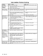
Page 20: ... page 23 bent terminal forks or other metal to metal contact points which could cause a short 2 Correct faulty conditions 3 Check motor armature for shorts Use an armature tester growler or perform motor test See page 18 Inspect windings for burns 3 Replace motor See page 28 4 Check motor control board 47 by substituting with a good board CAUTION Do not perform this check until motor armature is d...

Page 21: ...socket wrench pump inlet valve 1 2 open end wrench pump rod 11 16 open end wrench piston jam nut 15 16 open end wrench flats of inlet tube 1 3 4 open end wrench pump jam nut 5 64 drive pin drain valve pin 3 needle nose pliers wiring on off switch Hammer punch packing nut Torque wrenches various fasteners CAUTION To reduce the risk of a pressure transducer mal function properly mate connectors and ...

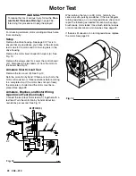
Page 22: ... hand If there are no shorts the motor will coast two or three revolutions before coming to a complete stop If the motor does not spin freely the armature is shorted and the motor must be re placed See page 28 Armature Brushes and Motor Wiring Open Circuit Test Continuity Connect the two black motor leads C together with a test lead Turn the motor fan by hand at about two revolutions per second Se...

Page 23: ...also 6 Repeat for the other side 7 Place a new brush C in the holder A Slide the terminal under the terminal screw washer E En sure the motor lead B is still connected at the screw Tighten the screw See Fig 15 8 Holding the spring clip F at a slight angle slide the spring clip into the brush holder and hook it over the end of the holder G See Fig 16 Pull on the spring clip to be sure it stays in p...

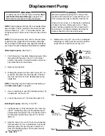
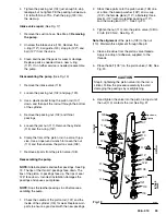
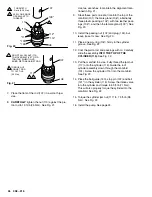
Page 24: ...a screwdriver to push the retaining spring 18 up and push out the pin 17 5 Loosen the screws 21 Remove the pump 20 Installing the pump See Fig 17 and 18 1 Lightly grease or oil the transducer 29 See Fig ure XX Guide the pump over the alignment pins and pressure transducer Tap it into position with a soft hammer Tighten the screws 21 to 50 ft lb 68 N m 2 Align the hole in the rod 107 with the conne...

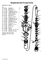
Page 25: ...ps of the throat V packings face down The lips of the piston V packings face up The lips of seal 125 face down Incorrect installation damages the packings and causes pump leaks NOTE Soak the leather packings in oil before reas sembling the pump 1 Check the outside of the piston rod 107 and the inside of the cylinder 115 for wear Replace worn parts to ensure a good seal with the new packings 2 Stac...

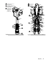
Page 26: ... 105 and then the female gland 103 See Fig 23 10 Install the packing nut 102 and plug 124 but leave loose for now See Fig 23 11 Place a new o ring 116 firmly in the cylinder groove See Fig 22 12 Coat the piston rod and packings with oil Carefully slide the assembly INTO THE TOP OF THE CYLINDER 115 See Fig 22 13 Put the manifold in a vise Fully thread the jam nut 117 onto the cylinder 115 Guide the...

Page 27: ...NTAKE VALVE 118 INTO CYLINDER 115 TO 53 ft lb 71 N m TORQUE JAM NUT 117 73 ft lb 98 N m Fig 22 01072A 105 104 LEATHER 113 LEATHER PLASTIC TORQUE TO 53 ft lb 71 N m 112 PLASTIC 114 122 121 101 117 106 116 103 110 111 115 120 119 118 107 102 108 123 Fig 23 125 126 03147 Lips face down Lips face up ...

Page 28: ...with the bottom drive housing screw 19 See Fig 25 Remove the three drive housing screws and lockwashers 19 6 See Fig 25 and 26 8 Remove the two motor screws and lockwashers 5 6 9 Tap the lower rear of the drive housing 11 with a plastic mallet to loosen the motor Pull the drive housing straight off the motor while guiding the harness A from the motor Do not allow the gear 16 to fall Read the CAUTI...

Page 29: ...ws 56 75 and lower the control card 47 See Fig 26 2 Disconnect the power supply cord leads P in cluding the green wire to the grounding screw 9 See Fig 12 3 Loosen the strain relief bushing 51 Remove the power supply cord 50 4 Install the new cord 50 in the reverse order of disassembly 5 Install the control card Be sure no leads are pinched between the card and other components On Off Switch WARNI...

Page 30: ...balls 11a or 4a or let them fall between the gears which will damage the drive housing if not removed The balls which are heav ily covered with grease usually stay in the gear recesses but could be dislodged If the balls are not in place the bearings will wear prematurely 7 Remove and inspect the crankshaft 12 and the connecting rod 15 Replace all damaged or worn parts 8 Install the connecting rod...

Page 31: ... 56 6 15 11 6 5 12a 12 12b 29 11a A 16 47 Fig 28 Note Filter not shown TORQUE TO 80 in lb 9 N m 02995 19 TORQUE TO 80 in lb 9 N m C B ...

Page 32: ...ed or if leakage occurred See page 33 Installation 1 Using a small piece of solid copper or mild steel wire approx 12 form a small hook and place it in the passage of the bottom of the motor Guide it up and out the hole in the drive housing 2 Pass a spacer 76 over the harness connector A and down into position at the bottom of the trans ducer 29 3 Guide the harness up through the leg and notch of ...

Page 33: ...anifold 101 3 Remove the packing and clean the manifold recess with solvent and cloth or cotton swabs Inspect for nicks or scratches in the o ring area Installation 1 Lightly coat the cleaned packing recess in the manifold with a light grease or oil 2 Heat the packing 7 in hot water for several minutes 3 Using fingertips or a blunt wooden or plastic probe install the packing into the recess Be car...

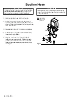
Page 34: ...d the hose will sep arate from the tube 3 Replace the o ring 27 if it is worn or damaged 4 Lubricate the o ring 27 and the inlet tube 38 threads with light grease 5 Align the suction hose coupling A with the threads of the inlet tube 38 Tighten the hose onto the tube at least 4 turns to ensure that the threads have disengaged and can function as a swivel joint CAUTION Misalignment or cross threadi...

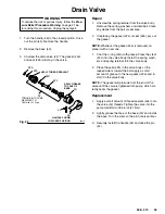
Page 35: ...ea 2 If replacing the gasket 42a or seat 42b pry out the gasket NOTE Whenever the gasket 42a is removed re place it with a new one 1 Coat the o ring 42d with grease Press the stem 42c into the valve body Install the spring wash ers and spring retainer into the valve body 2 Place the seat 42b in the valve body so the lapped side is toward the ball Apply a small amount of grease to the new gasket 42...

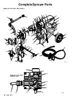
Page 36: ...67 74 34 13 85 32 33 44 43 20 36 45 42c 42d 42a 42b 27 38 10 28 12a 12 11a 16 12b 4a 11 6 15 17 18 56 02999 40 57 22 1 60 86 2 2a 2d 25 75 47 35 19 77 8 9 46 4 5 6 9 2e 2b 2c 71 73 59 70 76 29 7 72 20a 66 Pressure Control Box Bottom View 03020 69 64 48 65 50 51 49 55 54 52 ...

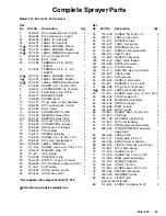
Page 37: ... spring 1 32 187 624 HOSE suction swivel 1 33 187 652 HOSE assy drain 1 Not supplied with sprayer Model 231 325 Extra Warning Labels available free Ref No Part No Description Qty 34 107 209 SCREW filh 8 32 x 1 0 4 35 189 111 LABEL cover front 1 36 111 612 ADAPTER tube 1 38 187 627 TUBE inlet swivel 1 39 235 004 STRAINER 3 4 unf 1 40 112 607 WHEEL semi pneumatic 2 42 235 014 VALVE drain 1 42a 111 6...

Page 38: ...c piston 3 113 176 749 V PACKING leather piston 2 114 180 073 GLAND female piston 1 115 235 708 CYLINDER pump 1 116 108 526 PACKING o ring PTFE 1 117 187 614 NUT jam 1 3 8 18 unef 2b 1 118 224 966 INLET VALVE 1 119 111 603 PACKING o ring PTFE 1 120 176 760 GUIDE ball 1 121 105 445 BALL 1 2 inlet 1 122 176 759 PIN ball stop 1 123 180 656 PLUG 1 124 102 969 SEALANT 1 125 105 522 PACKING u cup polyur...

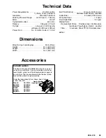
Page 39: ... Pump Stainless steel Carbon steel Aluminum Polyethylene Delrin Leather Filter Aluminum Steel PTFE Stainless steel NOTE D Dimensions Weight dry w o packaging 50 lb 23 kg Height 21 in 533 mm Length 22 in 559 mm Width 15 in 381 mm Accessories DANGER LABELS The English language DANGER label shown on page 1 is also on your sprayer If you have painters who do not read English order one of the following...

Page 40: ... defective parts The equipment will be returned to the original purchaser transportation prepaid If inspection of the equipment does not disclose any defect in material or workmanship repairs will be made at a reasonable charge which charges may include the costs of parts labor and transportation DISCLAIMERS AND LIMITATIONS The terms of this warranty constitute purchaser s sole and exclusive remed...

Reviews: