
Pressure Transducer
WARNING
To reduce the risk of serious injury, follow the
Pres-
sure Relief Procedure Warning
on page 21 be-
fore doing this procedure. Unplug the sprayer!
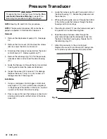
NOTE:
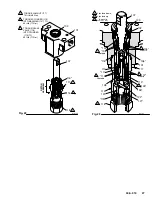
See Fig. 28 and 29 for this procedure.
NOTE:
The pressure transducer (29) cannot be re-
paired or adjusted. If it malfunctions, replace it.
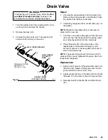
Removal
1. Remove the displacement pump (20). See page
24.
2. Remove the front cover (13). Remove the screws
(56,75). Lower the motor control card.
3. Disconnect the harness connector from the motor
control board (47). Remove grommet (77).
4. Remove the retaining ring (72). Pull the pressure
transducer down and out past the drive housing
(11).
5. Guide the harness (A) through the motor and drive
housing and remove the pressure transducer.
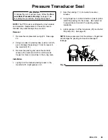
6. Inspect the spacer (76) and seal (7) for damage.
Replace the seal (7) only if it is cut, nicked, or if
leakage occurred. See page 33.
Installation
1. Using a small piece of solid copper or mild steel
wire (approx. 12”), form a small hook and place it
in the passage of the bottom of the motor. Guide it
up and out the hole in the drive housing.
2. Pass a spacer (76) over the harness connector (A)
and down into position at the bottom of the trans-
ducer (29).
3. Guide the harness up through the leg and notch of
the drive housing (11). Secure the guide wire over
the connector.
4. While pulling the guide wire out through the bottom
of the motor, guide the harness through the drive
housing and motor castings.
5. Place the grommet (77) over the harness and push
into position in the drive housing hole.
6. Feed the excess harness cable through the
grommet and fully seat the transducer body into
the hole in the drive housing leg. Secure it with
the retaining ring (72).
7. Attach the connector to the control board.
Replace the cover(13) and board (47) taking care
not to pinch any wires between the components.
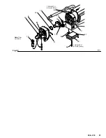
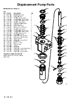
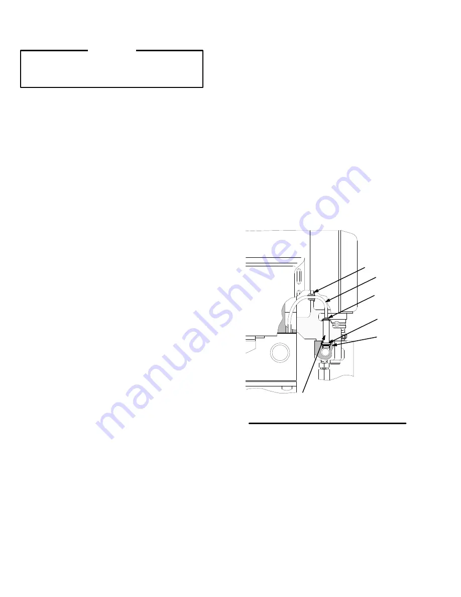
Fig. 29
02996
29
77
72
A
76
7


