background image

8

308842

Troubleshooting

MOTOR IS HOT AND RUNS INTERMITTENTLY

TYPE OF PROBLEM

WHAT TO CHECK

If check is OK, go to next check

WHAT TO DO

When check is not OK refer to this column

Motor is hot and runs intermit-
tently.

1. Determine if sprayer was operated at high

pressure with small tips, which causes low
motor RPM and excessive heat build up.

1. Decrease pressure setting or increase tip

size.

2. Be sure ambient temperature where sprayer

is located is no more than 90

F and sprayer

is not located in direct sun.

2. Move sprayer to shaded, cooler area if pos-

sible.

3. Determine if sprayer was turned on, pressur-

ized, but not operating for long periods of time.

3 Turn off sprayer whenever you stop spray-

ing for a while and relieve fluid pressure.

ELECTRICAL SHORT

TYPE OF PROBLEM

WHAT TO CHECK

If check is OK, go to next check

WHAT TO DO

When check is not OK refer to this column

Building circuit breaker opens
as soon as sprayer switch is
turned on.

1. All electrical wiring for damaged insulation, and

all terminals for loose fit or damage. Also wires
between pressure control and motor. See page
16.

1. Repair or replace any damaged wiring or

terminals. Securely reconnect all wires.

2. For missing inspection plate gasket (see page

16), bent terminal forks or other metal to metal
contact points which could cause a short.

2. Correct faulty conditions.

3. Motor armature for shorts. Use an armature

tester (growler) or perform spin test. See page
9. Inspect windings for burns.

3. Replace motor. See page 16.

4. Motor control board (104) by performing motor

control board diagnostics on page 12. If diag-
nostics indicate, substitute with a good board. 

CAUTION:

 Do not perform this check until mo-

tor armature is determined to be good. A bad
motor armature can burn out a good board.

4. Replace with a new pressure control board

(104). See page 12.

1. Basic Electrical Problems on page 4.

1. Perform necessary procedures.

2. ON/OFF switch (80) See page 11. 

Be sure

sprayer is unplugged!

 Disconnect wires from

switch. Check switch with ohmmeter. Reading
must be infinity with ON/OFF switch OFF, and
zero with switch ON.

2. Replace ON/OFF switch. See page 11.

3. For damaged or pinched wires in pressure con-

trol. See page 12.

3. Replace damaged parts. See page 12.

Sprayer quits  after sprayer op-
erates for 5 to 10 minutes.

1. Basic Electrical Problems on page 4.

1. Perform necessary procedures.

2. Electrical supply with volt meter.

Meter must read:
210–250 VAC for models 232144, 145, 154.
100–120 VAC for models 232148, 158.
90–110 VAC for models 232156, 157.

2. If voltage is too high, do not operate

sprayer until corrected.

3. Tightness of pump packing nut. Over tightening

tightens packings on rod, restricts pump action,
and damages packings.

3. Loosen packing nut. Check for leaking

around throat. Replace pump packings, if
necessary. See page 17.

CAUTION

Any short in any part of the
motor power circuit will cause
the control circuit to inhibit
sprayer operation. Correctly
diagnose and repair all shorts
before checking and replac-
ing control board.

Building circuit breaker opens
as soon as sprayer is plugged
into outlet and sprayer is NOT
turned on.

Summary of Contents for ultra max 1095

Page 1: ...boy 232157 A Ultra Max 1095 Lo boy Table of Contents Component Function and Identification 2 Grounding 4 Troubleshooting 4 Spin Test 9 General Repair Information 3 Motor Brush Replacement 9 On Off Switch Replacement 11 Pressure Control Repair 12 Bearing Housing Connecting Rod Replacement 14 Drive Housing Replacement 15 Motor Replacement 16 Displacement Pump Repair 17 Parts Drawing Sprayer 18 Parts...

Page 2: ...let pressure K Pressure Control Controls motor speed to maintain fluid outlet pressure at displacement pump outlet Works with pressure adjusting knob L ON OFF Switch Power switch that controls VAC main power to sprayer M 3 ft 0 9 m Hose 3 16 in ID grounded nylon hose used between 50 ft hose and spray gun to allow more flexibility when spraying N 50 ft 15 m Main Hose 1 4 in ID grounded nylon hose w...

Page 3: ...possible solutions WARNING EXPLOSION HAZARD Motor and drive housing are very hot during operation and could burn skin if touched Flammable materials spilled on hot bare motor could cause fire or explosion Have motor shield in place during operation to reduce risk of burns fire or explosion CAUTION Do not run sprayer dry for more than 30 seconds to avoid damaging pump packings 4 Install motor shiel...

Page 4: ...ction manual for cleaning Basic Mechanical Problems 1 For frozen or hardened paint in pump 64 Use a screwdriver and carefully rotate fan at back of motor by hand See page 9 1 Thaw sprayer if water or water based paint has frozen in sprayer Place sprayer in warm area to thaw Do not start sprayer until thawed completely If paint hardened dried in sprayer replace pump packings See page 17 Displacemen...

Page 5: ...ge 16 7 Motor armature for shorts using armature tester growler or perform spin test See page 9 7 Replace motor See page 16 8 Motor control board 104 by performing motor control board diagnostics on page 12 If diag nostics indicate substitute with a good board CAUTION Do not perform this check until mo tor armature is determined to be good A bad motor armature can burn out a good board 8 Replace w...

Page 6: ...ng 5 Be sure male terminal blades are centered and firmly connected to female terminals Replace any loose terminal or damaged wiring Securely reconnect terminals 6 For loose motor brush leads and terminals See page 9 6 Tighten terminal screws Replace brushes if leads are damaged See page 9 7 For worn motor brushes which must be 1 2 in minimum See page 9 7 Replace brushes See page 9 8 For broken an...

Page 7: ...issing Be sure retainer spring 68 is fully in groove all around con necting rod See page 17 2 Connecting rod assembly 63 for damage See page 14 2 Replace connecting rod assembly See page 14 3 Be sure crank in drive housing rotates plug in sprayer and turn on briefly to check Turn off and unplug sprayer See page 15 3 Inspect drive housing assembly for dam age and replace if necessary See page 15 EX...

Page 8: ...dings for burns 3 Replace motor See page 16 4 Motor control board 104 by performing motor control board diagnostics on page 12 If diag nostics indicate substitute with a good board CAUTION Do not perform this check until mo tor armature is determined to be good A bad motor armature can burn out a good board 4 Replace with a new pressure control board 104 See page 12 1 Basic Electrical Problems on ...

Page 9: ...nnect red and black motor leads together with test lead Turn motor fan by hand at about two revolutions per second 2 If uneven or no resistance check for broken brush springs brush leads motor leads loose brush terminal screws motor lead terminals worn brushes Repair as needed page 9 3 If still uneven or no resistance replace motor page 16 Fig 3 G 82 F 8051A Motor Brush Replacement NOTE Replace br...

Page 10: ...brush holder C 8 Fig 5 Slide brush lead E under washer of termi nal screw D and tighten screw Be sure motor lead F is connected at terminal screw 9 Fig 6 Place spring H on brush G 10 Fig 6 Install spring clip A Push down to hook short slots K in brush holder C Fig 6 G K J C NOTE SPRING COIL DIRECTION A 01227 E H 11 Repeat for other side 12 Test brushes a Remove pump connecting rod pin b With spray...

Page 11: ...t four wires A from ON OFF switch 80 6 Press in on two retaining tabs on each side of ON OFF switch 80 and remove 7 Install new ON OFF switch 80 so tabs of switch snap into place on inside of pressure control housing 8 Connect four wires A to ON OFF switch 9 Install display connector B in plug C 10 Install pressure control cover 82 8052B Fig 7 82 80 A 8 C 28 116 102 59 31 99 89 105 106 81 E D 104 ...

Page 12: ...tch ON 4 Observe LED operation and reference following table LED BLINKS SPRAYER OPERATION INDICATES WHAT TO DO Once Sprayer runs Normal operation Do nothing Twice Sprayer runs Normal operation Do nothing Two times repeatedly Sprayer shuts down and LED continues to blink two times repeatedly Run away pressure Pres sure greater than 4500 psi 310 bar 31 MPa Replace motor control board See preceding M...

Page 13: ... Locked rotor Motor can not turn Repair or replace Sprayer stops Power is applied Pressure less than 200 psi 14 bar 1 4 MPa Increase pressure Pressure Control Transducer Removal 1 Relieve pressure page 3 2 Fig 7 Remove five screws 28 and cover 82 3 Disconnect lead E from motor control board 104 4 Remove strain relief bushing 116 5 Remove pressure control transducer 31 and packing o ring 59 from co...

Page 14: ... install it on new bearing housing 10 Inspect crank E for excessive wear and replace parts as needed Evenly lubricate inside of bronze bearing B with high quality motor oil Pack roller bearing C with bearing grease 11 Assemble connecting rod 63 and bearing housing 22 12 Clean mating surfaces of bearing and drive hous ings 22 67 13 Align connecting rod 63 with crank E and drive housing locating pin...

Page 15: ...67 Pull bearing housing and connecting rod straight off drive housing 6 Remove two drive housing screws 26 and lockwashers 20 7 Remove two lower screws 16 and lockwashers 20 and then two upper screws 16 and lock washers 20 from front of motor 73 8 Tap drive housing 67 with plastic mallet to loosen from front of motor 73 pull drive housing straight off 9 Apply approximately 4 oz of bearing grease t...

Page 16: ...rive housing 67 Gear cluster may stay engaged in motor front end bell or drive housing Do not lose thrust balls 90 or drop thrust balls between gears If thrust balls are caught between gears and not removed serious damage will occur to drive housing If thrust balls are not in place at each end of gear cluster bearings will wear prematurely 10 While supporting motor 73 to keep sprayer from tipping ...

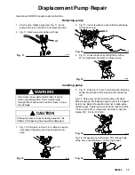
Page 17: ...us injury or prop erty damage CAUTION If the pump locknut loosens during operation the threads of the bearing housing will be damaged 1 Fig 14 Pull piston rod out 1 5 in Screw in pump until holes in bearing cross link and piston rod align Fig 14 7676B 1 5 in 2 Fig 12 Push pin 21 into hole And push retaining spring into groove all the way around connecting rod Fig 15 Screw jam nut down onto pump un...

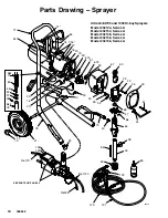
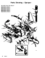
Page 18: ...es A Model 232148 Series A Model 232158 Series A Model 232156 Series A 8055A REF 77 SEE PARTS ON PAGE 22 33 Ref 70 Ref 85 32 68 24 61 66 39 53 47 40 70 78 20 16 30 77 54 34 16 20 73 90 67a 51 67b 90 67 63 22 23 25 49 26 20 30 10 73a 38 41 21 14 19 122 121 120 64 62 48 52 37 35 REF 78 85 Ref 120 41 84 65 126 123 ...

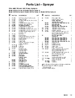
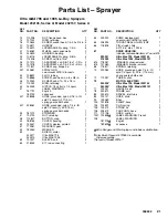
Page 19: ...ra Max 795 1 240313 Ultra Max 1095 1 61 192719 HANGER pail 1 62 192027 SLEEVE 2 63 218034 CONNECTING ROD 1 64 239923 DISPLACEMENT PUMP 1 see manual 308798 for parts 65 206994 THROAT SEAL LIQUID 8 OZ 1 66 176818 PIN straight hdls 1 0 3125 in dia x 1 023 in 67 DRIVE HOUSING 1 includes 67a and 67b 239931 Ultra Max 795 Model 232144 148 1 239929 Ultra Max 1095 1 Model 232154 158 218032 Ultra Max 1095 M...

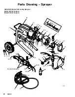
Page 20: ...yers Model 232145 Series A Model 232157 Series A 8126A 77 63 47 49 67 22 66 68 16 20 59 90 16 20 48 73 64 34 62 51 19 14 21 33 30 10 40 70 103 111 72 83 78 24 20 26 45 67a 67b 23 25 35 52 37 65 SEE PARTS ON PAGE 22 32 42 43 Ref 70 Ref 85 Ref 43 126 123 85 106 104 105 ...

Page 21: ...BUTTON snap 2 49 188154 COVER housing 1 50 193347 COVER display painted 1 51 179961 REDUCER gear 1 52 183350 WASHER 1 59 SHIELD motor 1 240317 Ultra MAX 795 1 240313 Ultra MAX 1095 1 62 192027 SLEEVE cart 2 63 218034 KIT rod connecting 1 64 239923 PUMP displacement 1 see manual 308798 for parts 65 206994 THROAT SEAL LIQUID 8 OZ 1 66 176818 PIN straight hdls 1 0 3125 in dia x 1 023 in 67 DRIVE HOUS...

Page 22: ...1 74 4 86 75 91 59 98 105 85 99 116 115 Ultra MAX 795 and 1095 Sprayers Model 232144 Series A Model 232145 Series A Model 232148 Series A Model 232154 Series A Model 232156 Series A Model 232157 Series A Model 232158 Series A 46 128 127 102 104 107 129 132 131 8 130 1 133 98 79 134 1 Model 232 148 and 232 158 only 2 1 ...

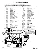
Page 23: ...EMBL Y drain valve 1 75 100721 PLUG pipe 1 76 186075 SUPPORT filter 1 79 CORD SET power see note page 22 1 240539 Continental Europe CEE 7 7 1 240540 Italy 1 239050 United Kingdom 1 240543 None Bare End 1 240721 Japan 1 241879 Australia 1 80 SWITCH rocker dpst 1 114518 Model 232144 145 148 154 158 1 114277 Model 232156 157 1 81 114273 KNOB potentiometer 1 82 240527 COVER control box painted 1 85 2...

Page 24: ...ord 14 AWG 1 5 mm2 3 wire 15 ft 4 5 m Inlet Paint Strainer 16 mesh 975 micron stainless steel screen reusable Outlet Paint Filter 60 mesh 238 micron stainless steel screen reusable m t p n 4 3 e z i S t e l n I p m u P Fluid Outlet Size 8 3 r e t l i F npt f Filter with standard 3 8 npt f to 1 4 npsm adapter 1 4 npsm Sound Data A B d 0 0 1 l e v e L r e w o P d n u o S A B d 0 9 l e v e L e r u s ...

Reviews: