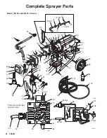
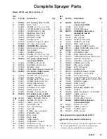
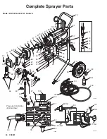
background image

308801

27 

Drive Housing, Connecting Rod, Crankshaft

7742A

25

4

12

2

4, 3

6

5

7

22

2a

A

13

22a

Fig. 23

Note:

 Filter

not shown

16

C

B

26

1

Torque to 80 in-lb (9 N

m)

1

1

Summary of Contents for ULTRA MAX 695 232133

Page 1: ...important warnings and information READ AND KEEP FOR REFERENCE ELECTRIC 120 VAC ULTRA MAX 695 Airless Paint Sprayer 3000 psi 210 bar 21 MPa Maximum Working Pressure Models 232133 and 232131 Series A Complete sprayer with hoses gun RAC IV DripLess Tip Guard and SwitchTip Model 232132 and 232130 Series A Basic sprayer only GRACO INC P O BOX 1441 MINNEAPOLIS MN 55440 1441 COPYRIGHT 1997 GRACO INC Gra...

Page 2: ...nstruction manuals tags and labels before operating the equipment Use the equipment only for its intended purpose If you are not sure call your distributor Do not alter or modify this equipment Use only genuine Graco parts Check equipment daily Repair or replace worn or damaged parts immediately Do not exceed the maximum working pressure of the lowest rated system component Refer to the Technical ...

Page 3: ...afety operates before spraying Lock the gun trigger safety when you stop spraying Follow the Pressure Relief Procedure on page 8 if the spray tip clogs and before cleaning checking or servicing the equipment Tighten all fluid connections before operating the equipment Check the hoses tubes and couplings daily Replace worn or damaged parts immediately Do not repair high pressure couplings you must ...

Page 4: ...cedure on page 8 to prevent the equipment from starting unexpectedly Liquids can be injected into the body by high pressure airless spray or leaks especially hose leaks Keep body clear of the nozzle Never stop leaks with any part of the body Drain all pressure before removing parts Avoid accidental trigger ing of gun by always setting safety latch when not spraying Never spray without a tip guard ...

Page 5: ... source through spray gun J 50 ft 15 m Main Hose 1 4 in ID grounded nylon hose with spring guards on both ends K RAC IV Tip Guard Reverse A Clean RAC tip guard reduces the risk of fluid injection injury L Contractor Gun High pressure spray gun with gun safety latch M RAC IV Switch Tip RAC switch tip uses high pressure fluid to remove clogs from spray tip without removing tip from spray gun N 3 ft ...

Page 6: ... Fill packing nut D Fill packing nut full with Graco Throat Seal Liquid TSL 64 supplied WARNING FIRE AND EXPLOSION HAZARD Proper electrical grounding is essential to reduce the risk of fire or explosion which can result in serious injury and property damage Read FIRE OR EX PLOSION HAZARD on page 4 and Grounding page 7 3 Plug in sprayer Be sure ON OFF switch E is OFF Plug cord into grounded outlet ...

Page 7: ...nual 307614 supplied How to use the pressure drain valve Use the pressure drain valve to relieve fluid pressure from the pump and to help prime the pump If the valve senses an over pressure condition it opens automati cally to relieve fluid pressure If this happens stop spraying immediately shut off and unplug the sprayer Determine the cause of the problem and correct it before operating the spray...

Page 8: ...G INJECTION HAZARD To reduce the risk of serious injury when instructed to relieve pressure follow the preceding Pressure Relief Procedure The tip guard alerts you to the risk of injection and helps prevent placing any part of the body close to the spray tip The tip guard also adjusts the vertical or horizontal spray pattern See page 10 The tip guard holds a reversing spray tip The tip is in the s...

Page 9: ...liter pail push drain hose D down below top of pail to avoid splashing paint when drain valve is opened 4 Turn pressure knob E to minimum setting 5 Disengage gun safety latch See Fig 4 CAUTION To reduce the risk of damage to the displacement pump packings never run the pump without fluid in it for more than 30 seconds 6 To prime pump turn sprayer ON OFF switch F ON Slowly increase pressure until s...

Page 10: ...ety latch first See manual 308644 for how to install tip 10 Adjust spray pattern a Increase pressure just until spray from gun is completely atomized To avoid excessive overspray and fogging and to extend tip and sprayer life always use lowest pressure needed to get desired results b If more coverage is needed use a larger tip rather than increasing pressure c Test spray pattern To adjust directio...

Page 11: ... housing after every 100 hours of operation Remove front cover Apply several drops of SAE 10 non detergent oil in bearing housing cavity B See Fig 10 CAUTION To prevent pump corrosion and to reduce the chance of fluid freezing in the pump in cold weather never leave water or any type of paint in the sprayer when it is not in use Freezing can seriously damage the sprayer or result in a loss of pres...

Page 12: ...lean water Latex Warm soapy water then clean water Mineral spirits Change colors same base Compatible solvent such as water or mineral spirits How to flush WARNING INJECTION HAZARD To reduce the risk of serious injury when instructed to relieve pressure follow the Pressure Relief Procedure on page 8 1 Relieve pressure 2 Remove spray tip and clean it separately If you are changing from water based ...

Page 13: ...s freely from gun Circulate solvent to thoroughly clean sprayer Release gun trigger Engage gun safety latch 8 Open drain valve and circulate solvent through drain hose to thoroughly clean it Close drain valve 9 Remove suction hose from pail Disengage gun safety latch Trigger gun and run pump a few seconds to push air into hose Do not run pump dry for more than 30 seconds to avoid damaging pump pac...

Page 14: ... 2 If tip is still clogged relieve pressure refer to separate gun or tip instruction manual for tip cleaning Clean or replace filter element See manual 308249 Mechanical 1 Check for frozen or hardened paint in pump 18 Using a screwdriver carefully try to rotate fan at back of motor by hand See page 23 1 Thaw After thawing plug in sprayer and turn it on Slowly increase pressure set ting to see if m...

Page 15: ... 22a to be sure they are securely fastened and properly mated 7 Replace loose terminals crimp to leads Be sure male terminal blades are straight and firmly connected to mating part 8 Check motor control board 22a by performing motor control board diagnostics on page 24 If diagnostics indicate substitute with a good board CAUTION Do not perform this check until motor armature is determined to be go...

Page 16: ...e pressure turn off and unplug sprayer 2 Service pump See page 22 3 Release gun trigger Observe resting position of pump rod 222 3 If pump consistently comes to rest with rod 222 fully extended the piston packings and or piston valve may be worn Service the pump See page 22 4 Check electrical supply with volt meter Meter should read 105 125 VAC 4 Reset building circuit breaker replace building fus...

Page 17: ...remove particles that could clog pump 5 Check for leaking around throat packing nut which may indicate worn or damaged packings See page 22 5 Replace packings See page 22 Also check piston valve seat for hardened paint or nicks and replace if necessary Tighten packing nut wet cup 6 Release gun trigger Observe resting position of pump rod 222 6 If pump consistently comes to rest with rod 222 fully ...

Page 18: ...to metal contact points which could cause a short 2 Correct faulty conditions 3 Check motor armature for shorts Use an armature tester growler or perform motor test See page 18 Inspect windings for burns 3 Replace motor See page 23 4 Check motor control board 22a by performing motor control board diagnostics on page 24 If diagnostics indicate substitute with a good board CAUTION Do not perform thi...

Page 19: ...to disconnect it 1 When disconnecting wires use needle nose pliers to separate mating connectors 2 When reconnecting wires center flat blade of male connector in blade of female connector 3 Route wires carefully and avoid pinching any wires between covers CAUTION Improper wire routing can result in poor sprayer performance or damage to the pressure transducer 4 Keep all screws nuts washers gaskets...

Page 20: ...there are no shorts the motor will coast two or three revolutions before coming to a complete stop If the motor does not spin freely the armature is shorted and the motor must be replaced See page 23 Armature Brushes and Motor Wiring Open Circuit Test Continuity 1 Connect red and black motor leads C together with a test lead Turn motor fan by hand at about two revolutions per second See Fig 13 786...

Page 21: ...shop if brushes seem to wear too fast or arc excessively See Step 9 d also 5 Repeat for other side 6 Place a new brush C in holder B so ramp H faces spring See Fig 15 7 Holding spring clip F at a slight angle slide spring clip into brush holder and hook it over end of holder See Fig 16 Pull on spring clip to be sure it stays in place Connect brush lead to blade con nector E 8 Repeat for other side...

Page 22: ...se a screwdriver to push retaining spring 15 up and push out pin 14 7 Loosen screws 17 Remove pump 18 Repairing pump See manual 308815 for displacement pump repair instructions and parts Installing pump See Fig 17 and 18 14 201 15 Fig 18 202 7840A 1 Lightly grease or oil transducer 67 See Fig 24 Guide pump over alignment pins and pressure transducer Tap it into position with a soft hammer Tighten ...

Page 23: ...d junction box 20 Refer to Fig 21 and 13 5 Remove drive housing cover 11 6 Turn displacement pump rod 222 so pin hole aligns with bottom drive housing screw 16 See Fig 20 Remove three drive housing screws and lockwashers 16 4 See Fig 20 and 21 7 Remove two motor screws and lockwashers 3 4 8 Tap lower rear of drive housing 2 with a plastic mallet to loosen motor Pull drive housing straight off moto...

Page 24: ...box Motor control board diagnostics 1 Relieve pressure 2 Remove screws 25 26 and lower heat sink 22 and motor control board 22a See Fig 21 3 Turn ON OFF switch ON 4 Observe LED operation and reference following table LED BLINKS SPRAYER OPERATION INDICATES WHAT TO DO Once Sprayer runs Normal operation Do nothing Twice Sprayer runs Normal operation Do nothing Twice repeatedly Sprayer shuts down and ...

Page 25: ...tch WARNING INJECTION HAZARD To reduce the risk of serious injury when instructed to relieve pressure follow the Pressure Relief Procedure on page 8 1 Relieve pressure 2 Remove screws 25 26 and lower heat sink 22 See Fig 23 3 Remove rubber boot 82 See page 32 4 Disconnect black wires from ON OFF switch 80 and remove switch See Fig 13 5 Install switch so internal tab of anti rotation ring 54 engage...

Page 26: ...grease usually stay in the gear re cesses but could be dislodged If the balls are not in place the bearings will wear prematurely 7 Tap lower rear of drive housing 2 with a plastic mallet to loosen motor Pull drive housing straight off motor 8 Remove and inspect crankshaft 5 and connecting rod 12 Replace all damaged or worn parts 9 Install connecting rod 10 Lubricate inside of connecting rod beari...

Page 27: ...308801 27 Drive Housing Connecting Rod Crankshaft 7742A 25 4 12 2 4 3 6 5 7 22 2a A 13 22a Fig 23 Note Filter not shown 16 C B 26 1 Torque to 80 in lb 9 N m 1 1 ...

Page 28: ...p and out the hole in the drive housing 2 Pass a spacer 68 over harness connector A and down into position at bottom of transducer 67 3 Guide harness up through leg and notch of drive housing 2 Secure guide wire over connector 4 While pulling guide wire out through bottom of motor guide harness through drive housing and motor castings 5 Place grommet 65 over harness and push into position in drive...

Page 29: ... reduce the risk of serious injury when instructed to relieve pressure follow the Pressure Relief Procedure on page 8 1 Relieve pressure 2 Remove drain hose 50 from clip 3 Pull upward on suction hose 47 while unscrewing it from inlet tube 43 The hose coupling A threads will engage and the hose will separate from the tube 4 Replace o ring 45 if it is worn or damaged 5 Lubricate o ring 45 and inlet ...

Page 30: ... Remove spring washers and stem ball Clean any debris from ball or seat area 2 If replacing gasket 55 or seat 56 pry out gas ket NOTE Whenever gasket 55 is removed replace it with a new one 3 Place seat 56 in drain valve assembly 51 so lapped side is toward ball Apply a small amount of grease to new gasket 55 and install it in drain valve assembly NOTE The gasket will protrude from the end of the ...

Page 31: ...ne Delrin Leather Tungsten carbide Chrome plating Polyurethane NOTE Delrin Dimensions Models 232132 and 232133 Models 232130 and 232131 Weight dry w o packaging 61 lb 27 7 kg Length 25 5 in 648 mm Width 15 in 381 mm Height 20 in 508 mm Weight dry w o packaging 73 lb 33 1 kg Length 21 in 533 mm Width 20 5 in 521 mm Height Handle Down 28 5 in 711 mm Accessories DANGER LABELS The English language DAN...

Page 32: ...2 4 12 14 15 25 39 38 40 70 37 31 32 57 42 26 22 35 16 65 8 9 75 85 3 4 9 60 23 24 20 21 68 67 69 66 100 74 70 Ref 71 72 73 Ref 73 Ref 19 73 Model 232132 and 232133 Series A Pressure Control Box Bottom View 76 77 27 30 29 78 82 81 80 17 55 56 28 22a 33 103 64 99 95 97 67 Ref 30 Ref 78 22a 96 107 108 77 Ref 80 Ref 7869B ...

Page 33: ...lain 2 41 100069 BALL thrust 1 42 112759 PLUG tube 2 43 192808 TUBE suction 1 44 235004 STRAINER 1 2 npsm 1 45 104938 PACKING o ring 1 46 192644 NIPPLE long 1 4 npt x 1 4 npt 1 47 187624 HOSE suction swivel 1 48 240038 FILTER fluid 1 see manual 308249 49 114026 CLIP spring 1 50 187652 HOSE drain assy 1 51 235014 ASSEMBLY drain valve 1 includes 55 and 56 52 224807 VALVE base 1 53 111600 PIN grooved...

Page 34: ...5 25 40 38 70 37 31 79 33 42 26 22 35 16 65 8 9 75 85 3 4 9 23 24 20 68 67 69 66 100 39 Model 232130 and 232131 Series A Pressure Control Box Bottom View 76 77 28 30 29 78 82 81 80 19 45 98 47 71 72 74 73 56 17 7729A 32 27 55 51 21 22a 57 30 Ref 82 Ref 60 103 105 99 64 95 67 Ref 78 22a 96 107 108 77 Ref 7869B ...

Page 35: ...G tube 2 43 192809 TUBE suction 1 44 187190 STRAINER 1 2 npsm 1 45 112777 SCREW 8 32 x 38 2 46 193718 NIPPLE 1 4 npt x 1 4 npsm 2 47 190321 HANGER pail 1 48 240038 FILTER fluid 1 Manual 308249 49 192648 CLIP spring 1 51 235014 ASSEMBLY drain valve 1 includes 55 and 56 52 224807 VALVE base 1 53 111600 PIN grooved 1 54 187625 HANDLE drain valve 1 55 111699 GASKET seat valve 1 56 187615 SEAT valve la...

Page 36: ...o other remedy including but not limited to incidental or consequential damages for lost profits lost sales injury to person or property or any other incidental or consequential loss shall be available Any action for breach of warranty must be brought within two 2 years of the date of sale GRACO MAKES NO WARRANTY AND DISCLAIMS ALL IMPLIED WARRANTIES OF MERCHANTABILITY AND FITNESS FOR A PARTICULAR ...

Reviews: