


2.
For the fluid hose to fit properly, it must be
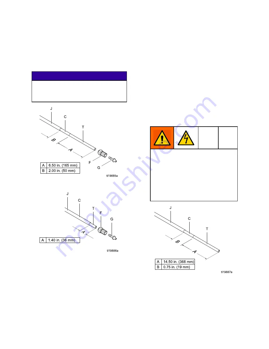
stripped and assembled to the dimensions shown
in Fig. 12. Apply dielectric grease to the inner
tube (T) of the hose. Slide the fitting (F) onto
the tube (T). Press the barbed fitting (G) into the
tube until its shoulder bottoms on the tube. A
new Graco waterborne fluid hose comes fully
assembled to these dimensions.
NOTICE
NOTICE
NOTICE
Be careful not to cut into the inner tube (T) of
the hose when stripping the hose. Nicks or
cuts in the PTFE tube will cause premature
hose failure.
Figure 12 Shielded Hose 24M732 Dimensions
at Gun
Figure 13 Unshielded Hose 24M733 Dimensions
at Gun
3.
Generously apply dielectric grease (44) to the
o-ring (107) and the threads of the fitting (106).
Pull the fitting back 1-1/2 in. (38 mm) and apply
grease to the exposed PTFE hose to fill the area
between the hose and the fitting. Make sure the
barrel inlet is clean and dry, then screw the fitting
into the fluid inlet of the gun barrel (1).
4.
Loosen the strain relief nut (102) so the bracket
can move freely on the hose.
5.
Align the bracket (104) holes with the air inlet and
exhaust outlet. Secure with the air inlet fitting
(21). Tighten the strain relief nut (102) to secure
the hose.
6.
Check that the nut (105) is tightened securely to
the ferrule housing (103).
7.
Press the exhaust tube (36) onto the exhaust
valve barb (C). Secure with the clamp (43).
8.
Connect the other end of the hose to the isolated
fluid supply as follows:
a.
Graco WB100 Enclosure:
Slide hose through
the strain relief fitting (W). Ensure conductive
layer (C) has passed through fitting. Tighten
to 55 in-lb (6.2 N•m). Pull back on hose to
check it is secure.
For
For
For Shielded
Shielded
Shielded Hose
Hose
Hose Systems:
Systems:
Systems:
Conductive hose layer (C) must be
grounded through its connection to the
isolation system’s grounded enclosure (L)
or grounded fence. To maintain grounding
continuity, the conductive hose layer (C)
must be engaged in the ferrule when the
strain relief nut is tightened. Failure to
properly install the hose in the strain relief
could result in an electric shock.
Figure 14 Shielded Hose 24M732
Dimensions at WB100 Enclosure
18
3A2496H


