13
307–959
SPRAYER REPAIR
WARNING
Always follow the
Pressure Relief Procedure
Warning
on page 8 before doing any repair.
Motor Repair
1. Remove the following: bottom cover (42), screws
(28), handle (32), shield (79), front cover (23). Refer
to the Parts Drawing.
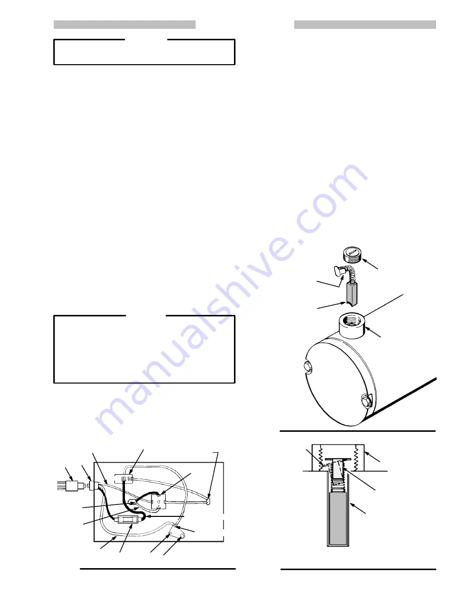
2. Disconnect the motor leads from the positive and
negative rectifier terminals. See Fig 11.
3. Remove the motor screws (20) and
lockwashers
(21). Lift the motor (30) slightly. Hold the connecting
rod while pulling the motor away from the housing
(22). See Fig 10.
4. Inspect the bearing (18b) in the connecting rod (18a).
If it is worn or any rollers are broken, replace the
bearing and rod assembly (18). See Fig 10.
5. Use your fingers to pack high–quality bearing grease
thoroughly between the bearing rollers. See Fig 10.
6. Guide the motor leads through the grommet (69).
Align the motor with the pins in the connecting rod
housing (22). Guide the motor eccentric through the
connecting rod bearing (18b). Spin the motor shaft to
be sure it moves freely. See Fig 10.
7. Loosely install the lockwashers (21) and screws (20).
Spin the motor shaft again. Alternately tighten the
screws. Spin the motor shaft again.
Spin the motor shaft while assembling the pump to
ensure that parts are properly aligned. If they are
not, and the pump is started, serious damage could
result to the motor, bearing, and connecting rod. If
there is binding or resistance, disassemble the
parts. Check the spin often until you determine the
cause of the binding.
CAUTION
8. Connect the red motor lead to the positive (+) termi-
nal and the black motor lead to the negative (–) termi-
nal of the rectifier (39). See Fig 11.
9. Reinstall all parts.
Fig 11
34
37 38
65
33 25
82,81,80
PRESSURE
SWITCH (2)
LEADS
JUMPER WIRE
GREEN WIRE
MOTOR
LEADS
WHITE
OUT
IN
RED
39
Motor Brush
1. Remove the bottom cover (42), screws (28), handle
(32) and shield (79). Refer to the Parts Drawing.
2. Remove the plug from each side of the motor and re-
move the brushes.
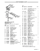
3. Install the new brush so its curve aligns with the
curve of the motor. See Fig 12.
4. Carefully push the copper contact into the brush
housing so its side tabs fit inside the holder. Tilt the
top of the contact so an edge of it catches in one of
the thread grooves. This holds the brush in place
temporarily. See Fig 13.
NOTE:
If necessary, start one tab into the holder , and
then use a small screwdriver to gently guide the
other tab into the holder.
5. Install the plug, applying even pressure so the brush
stays in place. If the plug does not turn in easily, re-
move it. Forcing the plug will damage the contact.
6. Repeat for the other side.
7. Reinstall all parts.
Fig 12
Fig 13
PLUG
Note curve of
brush. install curve
so it is parallel
with the curve of
the motor.
TABS OF
COPPER
CONTACT
BRUSH HOUSING
BRUSH HOUSING
Tabs of copper
contact fit squarely
in brush holder
Side view of brush installation does
not show curve of motor or brush
Tilt copper
contact so it is
held in place by
thread grooves in
brush housing.
BRUSH HOLDER


