background image

Setup 

6

3A2799D

Setup

System Requirements

Pressure drain valves are recommended in the system. 
Pressure drain valves assist in relieving fluid pressure in 
the displacement pump, hose and gun in the event that 
the gun is clogged and triggering the gun does not 
relieve all pressure.

Grounding

Check your local electrical code and pump or sprayer 
manual for detailed grounding instructions.

Spray gun:

 ground through connection to a properly 

grounded fluid hose and pump.

Pump:

 follow manufacturer’s recommendations.

Fluid hose:

 use only electrically conductive hoses with 

a maximum of 500 ft. (150 m) combined hose length to 
ensure grounding continuity. Check electrical resistance 
of hoses. If total resistance to ground exceeds 29 
megohms, replace hose immediately.

Fluid supply container:

 follow local code.

Object being sprayed: 

follow local code. 

Solvent pails used when flushing: 

follow local code. 

Use only conductive metal pails, placed on a grounded 
surface. Do not place the pail on a nonconductive 
surface, such as paper or cardboard, which interrupts 
grounding continuity.

To maintain grounding continuity when flushing or 
relieving pressure: 

hold metal part of the spray gun 

firmly to the side of a grounded metal pail, then trigger 
the gun.

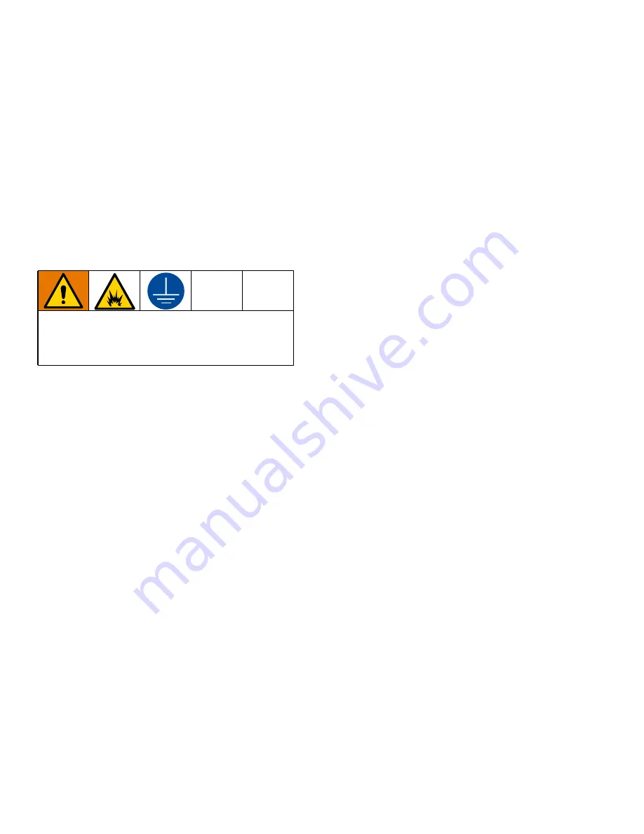
The equipment must be grounded to reduce the risk 
of static sparking. Static sparking can cause fumes to 
ignite or explode. Grounding provides an escape wire 
for the electric current.

Summary of Contents for XHF A Series

Page 1: ... XHD RAC Guard and XHD429 SwitchTip 7250 psi 50 MPa 500 bar Maximum Working Pressure Important Safety Instructions Read all warnings and instructions in this manual before using the equipment Save these instructions Important Medical Information Read the medical alert card provided with the gun It contains injection injury treatment information for a doctor Keep it with you when operating the equi...

Page 2: ...igger Lock 7 Tip Guard Installation and Removal 8 Spray 8 Adjust the Spray Pattern 8 Gun Care 9 Flushing 10 Maintenance 11 Disassemble the Gun 11 Reassemble the Gun 12 Test the Gun After Service 13 Parts 14 262854 14 26C793 15 Accessories 16 Technical Specifications 17 California Proposition 65 17 Graco Standard Warranty 18 Graco Information 18 ...

Page 3: ...raying and before cleaning checking or servicing equipment Tighten all fluid connections before operating the equipment Check hoses and couplings daily Replace worn or damaged parts immediately FIRE AND EXPLOSION HAZARD Flammable fumes such as solvent and paint fumes in work area can ignite or explode Paint or solvent flowing through the equipment can cause static sparking To help prevent fire and...

Page 4: ...ment is rated and approved for the environment in which you are using it Use equipment only for its intended purpose Call your distributor for information Route hoses and cables away from traffic areas sharp edges moving parts and hot surfaces Do not kink or over bend hoses or use hoses to pull equipment Keep children and animals away from work area Comply with all applicable safety regulations RE...

Page 5: ...y A Gun Body B Valve Seat C Gasket D Needle E Seal Retainer F Seal G SwitchTip H Tip Guard K Hex Screw L Set screw M Spring Guide N Socket Head Set screw P Spring Q Adjusting Screw R Fluid Housing S Pivot Pin T Gun Trigger U E Clip V Swivel W Trigger Pin Z Fluid Hose ZA Trigger Lock Key ...

Page 6: ... length to ensure grounding continuity Check electrical resistance of hoses If total resistance to ground exceeds 29 megohms replace hose immediately Fluid supply container follow local code Object being sprayed follow local code Solvent pails used when flushing follow local code Use only conductive metal pails placed on a grounded surface Do not place the pail on a nonconductive surface such as p...

Page 7: ... the gun is not in use always engage the gun s trigger lock if unit is being shut down or left unattended A wallet sized medical alert card with important injection treatment information is included with the gun Additional cards are available at no charge Provide a card to all operators Trigger Locked Trigger unlocked ti19265a no spray spray 1 To engage the gun trigger lock rotate the lock so it i...

Page 8: ...e may not improve the spray pattern and will cause premature tip and pump wear 7 If adjusting the pressure does not give a good spray pattern relieve pressure and try another tip size 8 When spraying use a full open full close trigger action to get uniform coverage of applied media Hold the gun about 14 in 350 mm from and at right angles to the work surface Do not swing the gun in an arc Practice ...

Page 9: ...rigger the gun into a pail or onto the ground to remove the clog 5 Engage the gun trigger lock 6 Rotate the tip handle back to the spraying position 7 Disengage the gun trigger lock and continue spraying 8 If the tip is still clogged a Engage the gun trigger lock b Follow the Pressure Relief Procedure page 7 c Remove the RAC SwitchTip and clean See Tip Guard Installation and Removal page 8 NOTICE ...

Page 10: ...l Put the pump intake in a grounded pail of compatible solvent 4 Start the pump at its lowest pressure 5 Single component systems only Trigger the gun into the original pail When flushing fluid appears release the trigger Two component systems only Trigger the gun into a waste container When flushing fluid appears release the trigger 6 Trigger the gun into the flushing fluid supply pail Circulate ...

Page 11: ... Q about 1 4 in 7 mm to release spring tension 3 Unscrew the valve seat B Remove the gasket C 4 Remove one e clip U then push the pin W out of the gun Remove the screw H pivot pin S and trigger T 5 Loosen the set screw L then remove the fluid housing R from the gun body A 6 While supporting the spring guide M to prevent bending the needle D loosen the set screws N then remove the spring guide M To...

Page 12: ...nstall the seal retainer E and torque to 30 40 in lb 3 4 4 5 N m 2 Lightly grease the small end of the needle D then guide it into the large end of the fluid housing R 3 Place the gasket C on the valve seat B Grease the threads of the valve seat B then install into the fluid housing R Torque to 20 25 ft lb 27 34 N m 4 Install the spring guide M and seat it against the needle Loosely thread both se...

Page 13: ...on one end of the trigger pin W Slide the pin through lower trigger holes and through the slot PS in the spring guide M turn the spring guide to align as needed Install the other e clip U onto pin 8 If it was removed install the spring tension screw Q at the rear of the gun Then turn the screw in until it stops Test the Gun After Service H ti19264a 1 Engage the gun trigger lock 2 Connect a hose to...

Page 14: ... SEAT valve 1 2b GASKET 1 2c NEEDLE 1 2d RETAINER seal 1 2e SEAL 1 8 XHD429 SwitchTip size 429 1 9 XHD001 KIT RAC Guard 1 13 203953 SCREW hex head 10 24 1 15 126943 SET SCREW 1 4 20 1 16 189960 GUIDE spring 1 17 112729 SET SCREW socket head 2 18 189958 PIN trigger 1 19 112727 SPRING 1 20 189990 ADJUSTER spring 1 21 110637 SCREW adjusting 1 22 16P780 HOUSING fluid 1 23 187965 PIN pivot 1 24 189974 ...

Page 15: ...960 GUIDE spring 1 17 112729 SET SCREW socket head 2 18 189958 PIN trigger 1 19 112727 SPRING 1 20 189990 ADJUSTER spring 1 21 110637 SCREW adjusting 1 22 26C792 HOUSING fluid 1 23 187965 PIN pivot 1 24 189974 TRIGGER gun 1 25 235468 STOP trigger 1 26 112410 E CLIP 2 28 222385 CARD medical alert not shown 1 34 18B903 GUARD trigger xhf 180 1 35 16P338 SCREW mach phillips rnd hd 1 36 107091 SCREW ma...

Page 16: ...nd seat This kit will decrease the maximum flow rate of the gun Accessories 17G981 Swivel 7250 psi 50 MPa 500 bar Maximum Working Pressure Connects the gun inlet to the fluid supply hose and allows easier gun movement and twisting 17G980 Swivel 7250 psi 50 MPa 500 bar Maximum Working Pressure Connects the gun inlet to the fluid supply hose and allows easier gun movement and twisting This swivel ha...

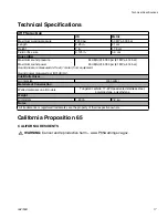
Page 17: ...d power 93 dB A 6000 psi 41 MPa 414 bar Sound pressure measured 3 3 feet 1 meter from equipment Sound power measured per ISO 9614 2 Inlet Outlet Sizes Air inlet size 3 8 npt m Materials of Construction Wetted materials on all models Tungsten carbide 17 4PH passivated stainless steel polypropylene polyethylene Weight All models 1 45 lb 7 2 kg Notes All trademarks or registered trademarks are the pr...

Page 18: ... TO WARRANTY OF MERCHANTABILITY OR WARRANTY OF FITNESS FOR A PARTICULAR PURPOSE Graco s sole obligation and buyer s sole remedy for any breach of warranty shall be as set forth above The buyer agrees that no other remedy including but not limited to incidental or consequential damages for lost profits lost sales injury to person or property or any other incidental or consequential loss shall be av...

Reviews: