Setup
22
3A4381M
Wire Systems with
Explosion-Proof Heaters
(Hazardous location systems only)
When explosion-proof heaters are used, ensure the
wiring, wiring connections, switches, and electrical
distribution panel all meet flame-proof (explosion-proof)
requirements.
Refer to the Viscon HF and HP heater manual for
electrical connection instructions and guidelines in
hazardous locations.
Motor Position
The motor position must be set for the volume mix ratio
of the system.
NOTE:
Changing the motor position does not change
the mix ratio.
Check Motor Position
1. Verify that the correct pumps are mounted for your
volume mix ratio. See chart in
Models
2. Verify that the motor position is adjusted correctly
for that volume mix ratio. If not, perform the
following
Change Motor Position
procedure.
Change Motor Position
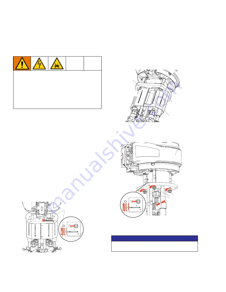
There are specific motor positions for each mix ratio
setting. To Adjust the position of the air motor:
1. Perform the
Check Motor Position
procedure. If
the position is incorrect, continue to the next step.
2. Loosen the eight fasteners and remove the two
pump guards.
3. Loosen the three nuts (107) below the motor tie
rods.
4. Slide the tie rods (102) and motor (E) until the
indicator lines are aligned with your ratio.
5. Tighten the three nuts (107).
6. Install the pump guards.
Improperly installed or connected equipment will
create a hazardous condition and cause fire,
explosion, or electric shock. Follow local regulations.
If your system is rated for hazardous areas, and you
have explosion-proof heaters, you must have a
qualified electrician connect the heater wiring. Make
sure the wiring and installation comply with local
electrical codes for hazardous areas.
WLF
Volume mix ratio
indicator lines
NOTICE
Do not hit the tie rods (P) with a hammer. Damage
to the air motor base may result.
WLD
fastener
pump guard
fastener
pump guard
Air Motor shown
WLF
9
9
(


