background image

3

309362

Symbols

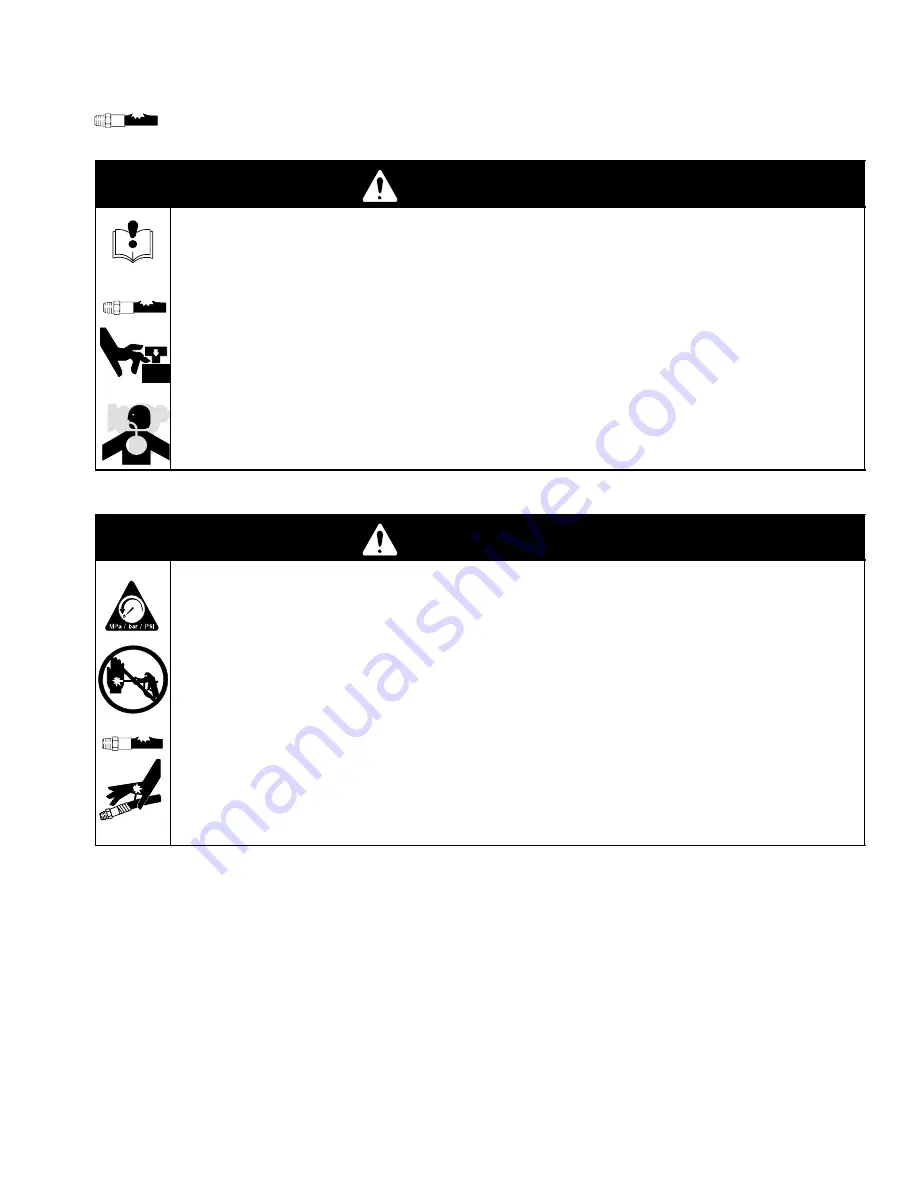
When you see a symbol in the manual, for example

 refer to the 

WARNINGS

 on pages 3–4.

WARNING

INSTRUCTIONS

EQUIPMENT MISUSE HAZARD

Equipment misuse can cause the equipment to rupture, malfunction, or start unexpectedly and result in serious
injury.

D

Read all instruction manuals, tags, and labels before operating the equipment.

D

Do not exceed the maximum working pressure of the lowest rated system component. 

See page 2 for maxi-

mum working pressure of each package.

D

Do not alter or modify equipment.

D

Do not use hoses to pull equipment.

D

Wear hearing protection when operating this equipment.

D

Moving parts can pinch or amputate your fingers.

D

Follow all local, state, and national fire, electrical, and safety regulations.

WARNING

PRESSURIZED FLUID AND INJECTION HAZARD

Spray from the gun, hose leaks, or ruptured components can splash fluid in the eyes or on the skin and cause
serious injury. High pressure spray or leaks can inject fluid into the body.

D

Follow 

Pressure Relief  Procedure

  on page 10 when you stop spraying or begin servicing sprayer.

D

Fluid injected into the skin might look like a cut, but is a serious injury. 

Get immediate medical attention.

D

Do not put your hand or fingers over the spray tip, or point gun at anyone or any part of body. Do not stop or
deflect leaks with your hand, body, glove, or rag.

D

Check the hoses, tubes, and couplings daily. Tighten all fluid connections before each use.

D

Know the specific hazards of the fluid you are using. Read the fluid manufacturer’s warnings.

D

Wear appropriate protective clothing, gloves, eyewear, and respirator.

D

Always have the tip guard and the trigger guard on the gun when spraying.

D

Check hoses and couplings daily. Replace worn or damaged parts immediately. Do not repair high pressure
couplings; you must replace entire hose.

Summary of Contents for Xtreme 244463

Page 1: ...49 OPERATION Zinc Sprayer List of Models page 2 For Maximum Working Pressure see page 2 INSTRUCTIONS IMPORTANT WARNINGS AND INFORMATION Read and keep for reference GRACO INC P O BOX 1441 MINNEAPOLIS MN 55440 1441 ECOPYRIGHT 2001 GRACO INC Graco Inc is registered to I S EN ISO 9001 ...

Page 2: ...t No Series Ratio Pump Pump No Gun Hose HD LW Maximum Fluid Working Pressure Maximum Air Input Pressure 244463 A 33 1 Bulldog 245117 X X X 20 7 MPa 207 bar 3000 psi 7 MPa 7 0 bar 100 psi 245113 A 24 1 Bulldog 245116 X X X 23 4 MPa 234 bar 3400 psi 7 MPa 7 0 bar 100 psi ...

Page 3: ...n hose leaks or ruptured components can splash fluid in the eyes or on the skin and cause serious injury High pressure spray or leaks can inject fluid into the body D Follow Pressure Relief Procedure on page 10 when you stop spraying or begin servicing sprayer D Fluid injected into the skin might look like a cut but is a serious injury Get immediate medical attention D Do not put your hand or fing...

Page 4: ... triggering into pail D Use only electrically conductive paint hose D If there is any static sparking while using the equipment stop spraying immediately Identify and correct the problem D Eliminate all ignition sources such as pilot lights cigarettes and static arcs from plastic drop cloths Do not plug in or unplug power cords or turn lights on or off in the spray area D To reduce the risk of sta...

Page 5: ...5 309362 ...

Page 6: ...6 309362 Overview Pump Air Regulator ON OFF 1 2 3 Loosen nut Tighten nut Adjust Air Air Supply Valve Must be Bleed Type Grounding Wire Return System ...

Page 7: ...lamp to a true earth ground 2 Ground object being sprayed fluid supply containers solvent pails waste pails and all other equipment in spray area Use only metal pails Do not place on non conductive surface such as paper cardboard or plastic PAINT TINTA PEINTURE INTURA TI1102 TI1102 ...

Page 8: ... 5 Tools Required 1 Two adjustable wrenches 2 Non sparking hammer or plastic mallet 3 Torque wrench 4 Grounding wires and clamps for pails 5 Two 5 gallon metal pails 1 Ground sprayer See page 7 2 Check packing nut Fill with Throat Seal Liquid TSL Torque to 25 30 ft lb 34 41 NSm ...

Page 9: ...lectrically conductive fluid hose to pump and tighten 4 Attach electrically conductive fluid hose to gun and tighten 5 Connect main air supply to air supply valve 6 Flush See page 11 FLUSH WASTE 7 Prime See page 14 WASTE PAINT ...

Page 10: ...elief Follow steps 1 3 when you stop spraying and before cleaning checking or servicing the equipment 1 Close bleed type air supply valve 2 Hold gun firmly against a grounded metal pail and trigger gun 3 Open return valve ...

Page 11: ...efore using for the first time changing colors before fluid can dry or settle out and before storing the system 1 Relieve pressure See page 10 2 Remove tip and guard 309092 308438 TI1114 3 Place suction tube in solvent FLUSH ...

Page 12: ... by turning handle counter clockwise 5 Open air valve Always use lowest air pressure possible when flushing 6 Flush hose and gun WASTE 309092 308438 ÏÏÏÏ ÏÏÏÏ 7 Put recirculation tube in a grounded waste pail Slowly open return valve WASTE ...

Page 13: ...ush 8 When clean solvent flows from tube close return valve Pump will stall WASTE 9 Relieve pressure See page 10 TI1217 ÏÏÏ ÏÏÏ 10 Store sprayer with solvent inside or prime with another fluid to continue spraying ...

Page 14: ...14 309362 Prime 1 Shut off bleed type air supply valve 2 Adjust air regulator by turning handle counter clockwise 3 Replace tip and guard 309092 308438 TI1114 4 Place suction tube in fluid PAINT ...

Page 15: ...2 Prime 5 Place recirculation tube in a grounded fluid pail Open return line valve PAINT 6 Open air valve 7 Adjust air regulator by turning handle clockwise until pump starts Use lowest air pressure to run pump ...

Page 16: ...e when material starts flowing 9 Hold gun firmly against a grounded metal pail and trigger gun until fluid flow is steady Release trigger Place recirculation tube into fluid to be sprayed Equip ment is ready to spray 309092 306686 308438 ...

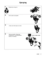
Page 17: ...2 Spraying 1 Replace tip and guard TI1114 2 Set air pressure regulator 3 Slowly open bleed type air valve 4 Test spray pattern Read fluid manufacturer s recommendations Adjust as necessary 309092 306686 308438 ...

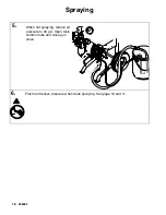
Page 18: ...18 309362 Spraying 5 When not spraying reduce air pressure to 30 psi Open recir culation tube and close gun valve PAINT 6 Flush and relieve pressure when done spraying See page 10 and 11 ...

Page 19: ...19 309362 Maintenance Daily 1 FLUSH ÏÏÏ ÏÏÏ 2 Relieve pressure See page 10 ÏÏ ÏÏ ÏÏ 3 Check packing nut Adjust packings and replace TSL as necessary Torque to 25 30 ft lb 34 41 NSm ...

Page 20: ...20 309362 Maintenance 4 Drain water from air filter 5 Clean suction tube using a compatible solvent Clean outside of sprayer using a cloth and compatible solvent ...

Page 21: ...21 309362 Maintenance 6 Check hoses tubes and cou plings Tighten all fluid connec tions before each use Troubleshooting 309340 ...

Page 22: ...Dimensions For mounting hole layout see air pump manual A B C Pump Model A mm in B mm in C mm in Weight approx kg lbs Bulldog 33 1 1257 49 5 795 31 3 660 26 236 107 Bulldog 24 1 1257 49 5 795 31 3 660 26 236 107 ...

Page 23: ...23 309362 ...

Page 24: ...h of warranty shall be as set forth above The buyer agrees that no other remedy including but not limited to incidental or consequential damages for lost profits lost sales injury to person or property or any other incidental or consequential loss shall be available Any action for breach of warranty must be brought within two 2 years of the date of sale Graco makes no warranty and disclaims all im...

Reviews: