background image

Section 2 - Pre-Operation and Controls

2-20

82104002

SAE Joystick Controls

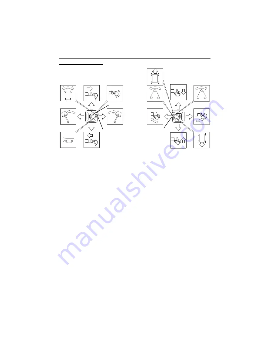
Left Hand Joystick Functions

• Move the joystick back to retract boom; move joystick forward to extend boom.

Move joystick right to swing boom right; move joystick left to swing boom left.

• Left-click steer control button (1) to turn front wheels left. Right-click steer control

button (1) to turn front wheels right.

• Attachment shake button (2) allows excess dirt or debris to be removed from the

boom attachment.

• For two simultaneous boom functions, move the joystick between quadrants. For

example, moving the joystick forward and to the left will extend and swing the
boom left simultaneously. 

Right Hand Joystick Functions

• Move the joystick back to raise boom; move joystick forward to lower boom.

Move joystick right to open tool; move joystick left to close tool.

• Left-click boom tilt button (3) to tilt boom counterclockwise; right-click boom tilt

button (3) to tilt boom clockwise.

• For two simultaneous boom functions, move the joystick between quadrants. For

example, moving the joystick forward and to the left will lower the boom and
close the tool simultaneously. 

2

3

OAC

264

0

1

Summary of Contents for D152

Page 1: ...chine at all times D152 D154 S N D152000001 After S N D154000001 After 82104002 Revised February 10th 2020 This manual and all manuals for the Gradall Hydraulic Excavator product line can be viewed or...

Page 2: ...ntrolled copy of the manual The current version can be viewed down loaded at www mygradall com Gradall is a registered trademark for hydraulic excavators industrial maintenance machines attachments an...

Page 3: ...ised torque specs on page 5 5 added torque spec for D154 Revised D152 specs on page 7 2 added specs for D154 Added s n range for PTO indicator on page 2 13 October 12th 2016 D Revised control scheme o...

Page 4: ...ed instructor Operators of this equipment must possess a valid applicable driver s license be in good physical and mental condition Operator must not be using medication which could impair abilities n...

Page 5: ...otified immediately in all instances where Gradall products have been involved in an accident involving bodily injury or death of personnel or when damage has occurred to personal property or the Grad...

Page 6: ...Read This First d 82104002 NOTES...

Page 7: ...azard 1 12 1 4 Personal Protection Equipment 1 13 Section 2 Pre Operation and Controls 2 1 Pre Operation Checks Inspection 2 1 2 2 Walk Around Inspection 2 2 2 3 Safety Decals 2 5 Decal Locations 2 5...

Page 8: ...g Upperstructure for Undercarriage Operation 3 22 Boom Stow Procedure 3 23 Securing Unit for Driving 3 23 3 10 Parking the Excavator 3 24 Precaution 3 24 Parking Procedure 3 24 3 11 Preservation Stora...

Page 9: ...res 6 1 Loss Of Power 6 1 Stowing the boom without engine power 6 1 To extend the boom without engine power 6 1 To raise the boom without engine power 6 1 Towing 6 2 If You Get Stuck 6 2 Section 7 Spe...

Page 10: ...Table of Contents iv 82104002...

Page 11: ...ING indicates a potentially hazardous situation which if not avoided could result in death or serious injury CAUTION indicates a potentially hazardous situation which if not avoided may result in mino...

Page 12: ...where overhead power lines overhead or underground cables or other power sources may exist without ensuring the appropriate power or utility company de energizes the lines Always check for power line...

Page 13: ...e Position machine to prevent possibility of a person being crushed between counterweight and another object Do not allow anyone inside the cab s other than the operator while in operation Always be c...

Page 14: ...y Practices 1 4 82104002 The circle of safety is a circle around the excavator with the boom at full extension Establish and inform others of the circle of safety Keep others from entering into the ci...

Page 15: ...or dismounting machine Repair or replace damaged steps and grab handles Keep grab handles steps and walkways free of mud oil grease and other foreign material Replace non skid surface material as req...

Page 16: ...resting on the ground and the engine is stopped Be sure all access covers are in the fully open position before performing any procedures inside compartments Stay clear of moving parts while engine is...

Page 17: ...General Safety Practices 1 7 82104002 Never permit anyone under boom attachment or load Rest boom or attachment on ground and stop engine before permitting anyone to work beneath boom or behind cradl...

Page 18: ...egard to undercarriage Confusion could cause travel in the opposite direction you may expect Always wear seat belt Keep head arms and other body parts inside cab at all times When machine is operating...

Page 19: ...o restrict movement Never pass load line over open bucket Relief valves in bucket circuit could cause unexpected dangerous movement of the load Bucket linkage could also be damaged Be sure the surface...

Page 20: ...e you to chemicals including gasoline diesel fuel lubricants petroleum products engine exhaust carbon monoxide and phthalates which are known to the State of California to cause cancer and birth defec...

Page 21: ...ical attention immediately Stop engine and relieve trapped pressure before loosening any hydraulic fitting Hydraulic oil is under enough pressure that it can penetrate the skin DO NOT attempt to repai...

Page 22: ...icosis Concrete masonry many types of rock and various other materials contain silica sand California lists respirable crystalline silica as a substance known to cause cancer Operation of this equipme...

Page 23: ...ditions You may need Hard hat Safety shoes Safety glasses goggles or face shield Heavy gloves Hearing protection Reflective clothing Wet weather gear Respirator or filter mask Wear adequate clothing f...

Page 24: ...Section 1 General Safety Practices 1 14 82104002 NOTES...

Page 25: ...ur local Division of Motor Vehicles for a list of Pre trip inspections that are recommended in the Commercial Driver s License CDL Manual These inspections should be performed before the inspections o...

Page 26: ...damage Chassis manuals in cab Grab handles and steps secure and clean Window glass and mirrors clean and unobstructed Adjust mirrors for maximum visibility before and during operation Be sure windows...

Page 27: ...ing hardware 8 AC Heater Cover Ensure cover is securely latched Replace damaged latches immediately 9 Rear Axle Fender Check mud flaps for proper position and condition for highway operation brakes un...

Page 28: ...nd refill as required Do not remove the radiator cap Be sure antifreeze solution is adequate for expected temperatures Be sure radiator and oil cooler fins are clean Drive belt check condition replace...

Page 29: ...5 82104002 2 3 SAFETY DECALS Ensure all DANGER WARNING CAUTION and instructional decals and proper capacity charts are legible and in place Clean and replace as required Decal Locations 80509015 80373...

Page 30: ...Section 2 Pre Operation and Controls 2 6 82104002 80509016 80509019 80509017 80509012 80509018 80509015 80509013 80373077 80509015...

Page 31: ...Section 2 Pre Operation and Controls 2 7 82104002 80509016 80509015 80509015 80783208 80509004 80509012 80509015...

Page 32: ...ATORS LCD Display The LCD display is a collection of controls and indicators The following pages provide detail of how to understand and function this unit starting at the top of the display to the bo...

Page 33: ...patterns by rotating the control panel dial 4 When desired control pattern is displayed press the Joystick Control Pattern Selection button 3 to confirm selection If a new pattern is selected controls...

Page 34: ...icator Illuminates red and pulsing alarm is activated when critical engine fault is detected Stop engine immediately and repair before continued use 7 Engine Warning Indicator Illuminates yellow when...

Page 35: ...el Indicator 3 Diesel Exhaust Fluid DEF Level Indicator 4 Transmission Gear Indicator See Driving Undercarriage from Upperstructure Cab on page 3 6 5 Transmission Oil Temperature Indicator 6 Hydraulic...

Page 36: ...Section 2 Pre Operation and Controls 2 12 82104002 n min AUTO n min 90 75 n min 9 1 2 3 4 5 5 a 6 8 8 a OAC2220 7...

Page 37: ...e control panel dial 9 clockwise Decrease engine throttle speed by rotating the control panel dial 9 counterclockwise When desired speed is attained press the Engine Throttle Speed button 5 6 Auto Idl...

Page 38: ...1 a No Auxiliary Hydraulic Control function is active 1 b Auxiliary Hydraulic Control function is operated by optional foot switch 1 c Auxiliary Hydraulic Control function is operated by the Attachme...

Page 39: ...Section 2 Pre Operation and Controls 2 15 82104002 This Page Intentionally Left Blank...

Page 40: ...od 1 Boom Tilt Speed Switch Rotary switch Rotate switch clockwise to decrease boom tilt speed rotate counterclockwise to increase boom tilt speed 2 Park Brake Switch See page 2 26 for details 3 AM FM...

Page 41: ...Hand Arm Pod 1 Fan Speed Rotary switch for heater and air conditioner fan 2 Boom Lights Switch optional On Off switch 3 Work Lights Switch optional On Off switch 4 Intermittent Wiper Washer Switch Se...

Page 42: ...Section 2 Pre Operation and Controls 2 18 82104002 NOTES...

Page 43: ...ntrol cut out lever 1 located on the left hand arm pod 2 is moved to the unlocked active position Joystick Control Patterns Before operating refer to the selected joystick control pattern located on t...

Page 44: ...chment For two simultaneous boom functions move the joystick between quadrants For example moving the joystick forward and to the left will extend and swing the boom left simultaneously Right Hand Joy...

Page 45: ...or two simultaneous boom functions move the joystick between quadrants For example moving the joystick forward and to the left will lower boom and open tool simultaneously Right Hand Joystick Function...

Page 46: ...attachment For two simultaneous boom functions move the joystick between quadrants For example moving the joystick forward and to the left will lower and swing boom left simultaneously Right Hand Joy...

Page 47: ...t Adjustments Prior to starting engine adjust seat for position and comfort 1 Height Adjustment Control 2 Upper Seat Fore and Aft Adjustment Control 3 Weight Control Adjustment 4 Lower Seat Fore and A...

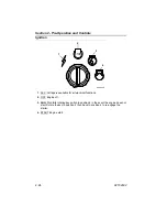
Page 48: ...ge is available for all electrical functions 2 OFF Engine off 3 RUN Prohibits rotating key switch to position 4 in the event the engine does not start Rotate the key to position 2 then back to positio...

Page 49: ...trols 2 25 82104002 Intermittent Wiper Washer 1 OFF 2 DELAY Rotating knob clockwise decreases delay 3 LOW Low wiper speed No delay 4 HIGH High wiper speed No delay 5 WASHER Press and hold switch to ac...

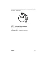
Page 50: ...LCD display illuminates red to indicate brake is applied With the engine running and the park brake switch in OFF position 1 park brake is disengaged With switch in ON position 2 park brake is engaged...

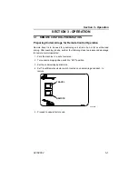
Page 51: ...not for over the road driving After reaching job site perform the following steps to prepare undercarriage for remote control operation 1 Park the machine in a safe level area 2 Turn undercarriage ign...

Page 52: ...e 2 19 2 Turn ignition switch to RUN position 3 The wait to start light will illuminate on LCD Display When light turns off move to step 4 Note Engine will not start when light is illuminated 4 Turn i...

Page 53: ...es and park brake function properly before traveling a significant distance in remote control Be sure travel alarm and horn function properly Both must be audible from the cab with engine running Make...

Page 54: ...will turn off when pressure reaches 70 psi Always apply upperstructure parking brake before leaving upperstructure cab Digging Brake When traveling in remote mode the digging brake is automatically a...

Page 55: ...Section 3 Operation 3 5 82104002 This Page Intentionally Left Blank...

Page 56: ...e Undercarriage speed is controlled by the amount of travel pedal actuation 1 Travel Pedal The travel pedal controls undercarriage travel speed 2 Brake Pedal Prior to Travel Depress fully to engage tr...

Page 57: ...ward travel With forward travel joystick button still depressed release brake pedal to begin travel Use the travel pedal 1 to increase decrease travel speed Forward travel joystick button must remain...

Page 58: ...reverse travel With reverse travel joystick button still depressed release brake pedal to begin travel Use the travel pedal 1 to increase decrease travel speed Reverse travel joystick button must rema...

Page 59: ...utton to turn front wheels left Right click steer control button to turn front wheels right UNEXPECTED DIRECTION OF TRAVEL Before remote travel check to be sure you are aware of orientation of upperst...

Page 60: ...or ventilation Remove boom tie down chain from boom 3 Perform checks before remote control operation located on page 3 3 Set engine to full throttle position 4 Be certain control cut out lever is in d...

Page 61: ...control pattern shown in illustration above Note Practice with controls in a safe open area Joysticks and pedals return to neutral position when released 1 Pull back on right joystick A to raise boom...

Page 62: ...pushing left joystick forward F to extend boom push right joystick forward B to lower boom into position for start of cut 4 Move right joystick to right C to open bucket or to left D to close bucket...

Page 63: ...clockwise 6 While pushing forward on right joystick B to lower boom and force bucket into ground pull back on left joystick E to retract boom and fill bucket 7 As bucket is filling jog right joystick...

Page 64: ...D to close bucket At same time pull right joystick back A to raise boom far enough to clear obstructions 9 Move left joystick to right H to swing right or to left G to swing left to dump site If nece...

Page 65: ...Section 3 Operation 3 15 82104002 11 Move left joystick to left G or right H to align boom for next cut Repeat steps 3 through 11...

Page 66: ...to the value on the lift capacity chart If it becomes necessary to shut the engine off while positioning a load place load on the ground prior to shutting off engine Be thoroughly familiar with excava...

Page 67: ...d delivery not the best The worst condition can only be determined by performing an UNLOADED TEST AND DELIVERY of the load Loads shown on chart in cab are hydraulic lift capacities with those in shade...

Page 68: ...ure boom height depth from hole in adapter to ground level same level as bottom of tire Be sure to allow for length of chain and height of load 5 Measure load radius from inner corner of frame at fron...

Page 69: ...lift capacity The rated lift capacity is based on the machine being equipped with 15 500 lb 7030 kg counterweight standard boom standard tires no auxiliary hydraulics and no bucket Adjust the listed...

Page 70: ...specified load radii and heights The weight of slings and any auxiliary devices must be deducted from the rated load to determine the net load that may be lifted ATTENTION All rated loads are based o...

Page 71: ...to engage digging brake 2 Swing the machine to align upperstructure with undercarriage 3 Lower attachment boom to ground or stow boom in boom rest See Boom Stow Procedure on page 3 23 4 Operate engine...

Page 72: ...al position to engage digging brake 2 Position boom in rest allowing clearance for attachment See Boom Stow Procedure on page 3 23 3 Apply parking brake 4 Shut down engine from upperstructure cab 5 Pr...

Page 73: ...trated Securing Unit for Driving Drive to and from job site only under the following conditions Boom is in boom rest Mirrors are clean and properly adjusted for visibility Doors and upperstructure win...

Page 74: ...rking on roads or highways If it cannot be avoided or in case of emergency display warning flags flares or flashing lights Parking Procedure 1 Turn off engine 2 Fill fuel tank to minimize condensation...

Page 75: ...s manufacturer manual for instructions or precautions prior to doing so Maintenance Take a sample of hydraulic fluid for analysis Note Not all analysis methods are compatible with all hydraulic fluids...

Page 76: ...Section 3 Operation 3 26 82104002 This Page Intentionally Left Blank...

Page 77: ...use unapproved attachments for the following reasons Gradall cannot establish range and capacity limitations for will fit homemade altered or other non approved attachments An overextended or overloa...

Page 78: ...Section 4 Attachments 4 2 82104002 Excavating Buckets Ditching Buckets Size 36 914mm Size 60 1 52m OAC0230 OAC2240...

Page 79: ...ure to comply could result in death or serious injury If guards are removed for service replace them before operating machine Do not step or stand on engine cover or upperstructure heater cover when p...

Page 80: ...g of engine oil to all linkage pivot points Drain engine and gear cases after operating when oil is hot Check all lubricant and coolant levels when cool MACHINE DAMAGE Contact Gradall before welding o...

Page 81: ...ance Schedule 50 Hour Maintenance Schedule OAC2350 10 EVERY Windshield Washer Fluid Bottle clean cab glass Mirrors clean and adjust for proper visibility Follow Lubrication Schedule OAC2360 50 EVERY C...

Page 82: ...AC2370 100 EVERY Check Boom Roller Alignment OAC2380 250 Drain and Refill Swing Transmission Oil Apply Open Gear Lube to Tilt Gear Teeth Follow Lubrication Schedule 250 EVERY Inspect Clean or Replace...

Page 83: ...EVERY Torque all Items Listed in Torque Chart LB FT Nm Remove Clean and Replace Swing Transmission Breather Follow Lubrication Schedule Check Tilt Transmission Level OAC2100 1500 EVERY Drain and Refi...

Page 84: ...Pins Telescoping Boom Rollers 3 places Hoist Cylinder Rod Ends Hoist Cylinder Barrel Pins Swing Bearing Tool Cylinder Barrel Pin Boom Cylinder Spherical Bearing Curved Straight Link Adapters Open Boom...

Page 85: ...002 5 5 UNDERCARRIAGE LUBRICATION SCHEDULE 10 Hr Weekly Tie Rod End Both Sides R H King Pin Top Bottom L H King Pin Top Bottom Steer Cylinder Barrel End Tie Rod at Steer Arm Steer Cylinder Rod End Sli...

Page 86: ...Section 5 Lubrication Maintenance 5 8 82104002 10 Hr Weekly Idler Arm Drag Link Front U Joint Slack Adjusters Brake Cam Shafts OAD0740...

Page 87: ...ract side of the boom circuit 2 Direct the rod side oil into a waste container as the boom is SLOWLY pulled out 3 Once the boom is at the proper extension secure the telescoping boom to the main boom...

Page 88: ...est hoses used for the procedure 14 Secure the telescope boom to keep it from extending and retracting 15 Follow the procedure on page 3 22 for shifting the machine into travel mode Towing Towing proc...

Page 89: ...9 liters Type of Fluid Conoco Heat Transfer 32 Hydraulic Fluid p n 80533049 Swing Transmission Capacity 2 47 quarts 2 3 liters Type of Fluid Gear Oil 80w90 p n 80533027 Swing Brake Capacity 4 ounces...

Page 90: ...pecification sheet for additional machine weight information Specification sheets can be viewed downloaded at www gradall com Dimensions D152 D154 Wheelbase 15 1 ft 4 8 m Ground Clearance 10 in 254 mm...

Page 91: ...chart DO NOT EXCEED allowances Boom Cylinder Mount Plate Quantity 19 Thread Size grade 5 8 11 5 Torque lubricated 200 215 lb ft 272 292 Nm Swing Bearing Quantity 68 Thread Size grade 5 8 11 8 Torque...

Page 92: ...ont axle u bolt nuts are torqued to 560 595 lb ft 8 nuts If replacement or torquing of nut s is required Remove nut s clear threads of existing loctite Clear threads of u bolt s of existing loctite Ap...

Page 93: ...ued to 560 595 lb ft 8 screws If replacement or torquing of cap screw s is required follow the pattern illustrated Torque bolts in a 4 stage criss cross pattern Stage 1 150 185 lb ft Stage 2 280 315 l...

Page 94: ...Section 7 Specifications 7 6 82104002 7 3 FUSES Fuse location and size designations are identified with the decals shown below Upperstructure Undercarriage OAD0680 OAD0690...

Page 95: ...nd Arm Pod 2 16 Lift Capacity 3 19 Lifting a Load 3 16 Load Falling Hazard 1 9 Lubrication Maintenance 5 1 Lubrication Schedule Undercarriage5 7 Lubrication Schedule Upperstructure 5 6 O Operation Rem...

Page 96: ...Index 2 82104002 Travel Hazard 1 8 U Upperstructure Cab Controls Indica tors 2 8...

Page 97: ...OVE SLOWLY Place one hand motionless in front of hand giving motion signal Raise load slowly shown EXTEND BOOM With both hands clenched point thumbs outward RETRACT BOOM With both hands clenched point...

Page 98: ...Gradall Industries Inc 406 Mill Ave SW New Philadelphia OH 44663 USA Phone 330 339 2211 Customer Support Toll Free 800 445 4752 Fax 330 339 3579 www gradall com...

Reviews: