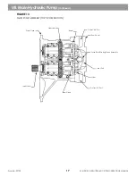
XL Series machines use a bent-axis, variable-displacement main pump to provide fluid to all hydraulic functions
(except swing and pilot). The main pump assembly contains a pump housing, pump end cover, pump splitter
box, two pump assemblies, pump stroking controls and an auxiliary drive PTO for other hydraulic pumps. Both
pump groups are connected to a single set of pump stroking controls that vary pump displacement in response
to system pressure. This works to constantly match hydraulic horsepower to engine horsepower during machine
operation.
The main pump assembly is bolted to the engine flywheel housing. The flexible coupling attached to the flywheel
drives the main pump assembly. A pump input shaft disconnect (clutch) is not provided. Gear sets within the
pump housing provide a splitter box to drive the pump rotary groups and the pump PTO drive.
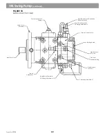
See Figure 13
Supply fluid from the hydraulic reservoir completely fills the main pump case. This fluid lubricates and cools internal
parts. It also works as suction fluid for both rotary groups of the main pump. When the system is exposed
to a vacuum, the hydraulic fluid is changed, or a pump is removed or changed, the pump housing must be
completely filled with clean hydraulic fluid and air purged before startup per instructions on pages 18 & 19.
Each pump group supplies fluid to a valve bank which then supplies fluid to machine hydraulic functions. A
diverter valve in the bucket/hoist/tilt valve bank allows excess pump flow within one valve bank to be made
available to functions within the other valve bank.
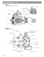
See Figure 14
Pump stroking controls are connected to port
A2 on the pump and valve load sensing circuit (sending a signal of the highest circuit pressure to the pump).
These stroking controls read the two pressure signals to change pump displacement as needed and to match
pump flow to hydraulic system requirements. When controls are not being used, the pump goes to standby and
maintains enough flow for standby pressure (300 - 350 PSI).
See Figure 15
The rotary groups in the main pump swivel from 25° at maximum stroke to 0° at minimum stroke. Swivel angle
depends upon system flow requirements and system pressure. Pump controls affect the swivel angle of the pump.
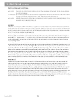
Main Hydraulic Pump Adjustments.
See 16
Pump Operation Adjustment Screws (3)
Located at the top of the pump end cover.
Horsepower Control Adjustment Screw
Located at the top and front of the main pump. Adjusts thepoint at which this control overrides load
sense control. Destrokes the pump to prevent overloading the engine. It is linked to the pump stroke
piston and uses pump angle and pump output pressure to determine operation.
Pump Cutoff Adjustment
Located behind the horsepower control. Reads the load sense pressure from the valves. Cuts off the
loadsense signal if pump output pressure is higher than the control setting. Prevents over-pressure
of the pump.
Load Sense Control
Located on the side of the pump control block. Maintains pressure differential between pump output
pressure and load sense signal. Constantly reads pump output pressure and load sense signal pressure.
Senses control valves as variable orifices and maintains a constant pressure drop across control valves.
Pressure differential is also known as main pump standby pressure. Plus, the maximum stroke control
should always be set to the maximum position (with no adjustment required). It is located at the bottom of
the pump end-cover.
VII. Main Hydraulic Pump
1.
2.
3.
4.
16
Form No. 29703
Summary of Contents for XL4000
Page 2: ......
Page 73: ......
Page 76: ... 5MP ...
Page 145: ......
Page 146: ......
Page 160: ......
Page 161: ......
Page 162: ......
Page 175: ......
Page 176: ......
Page 177: ......
Page 178: ......
Page 192: ......
Page 193: ......
Page 194: ......
Page 207: ......
Page 208: ......
Page 210: ...500P ...
Page 229: ......
Page 230: ......
Page 245: ......
Page 246: ......
Page 247: ......
Page 248: ......
Page 265: ......
Page 266: ......
Page 267: ......
Page 268: ......
Page 280: ......
Page 281: ......
Page 282: ......
Page 297: ......
Page 298: ......
Page 299: ......
Page 300: ......
Page 301: ......
Page 302: ......
Page 303: ......
Page 304: ......


