V
V
V
V
V..... Swing Cir
Swing Cir
Swing Cir
Swing Cir
Swing Circuit Pr
cuit Pr
cuit Pr
cuit Pr
cuit Pressur
essur
essur
essur
essure
e
e
e
e Adjustments
Adjustments
Adjustments
Adjustments
Adjustments
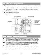
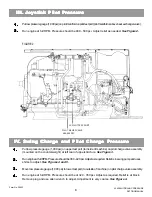
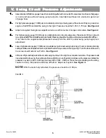
Assemble two GRADALL gauge hoses from test kit together with connector. Route across machine so that gauge
is in cab and hose will reach swing pump test ports. Carefully bleed hose into a bucket to get air out
of gauge hose.
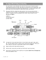
Put high pressure gauge (10,000 psi) on inside test port on top of swing pump. Place boom firmly on ground, run
engine at full RPM and stall the swing to the right. Pressure should be 5,450 - 5,750 psi.
See Figure 6.
Adjust as required. Swing torque adjustment screw is at front center of torque control valve.
See Figure 6.
Put high pressure gauge (10,000 psi) on outside test port on top of swing pump. Place boom firmly on ground,
run engine at full RPM and stall the swing to the left. Pressure should be the same as the previous test within 200 psi.
If not, refer to the supplemental pressures manual (Form No. 29416) under swing pump begin point
adjustment.
Leave high pressure gauge (10,000 psi) on outside test port to test swing cushioning. Check nominal cushioning
setting at brake valve adjustment screw (located behind torque valve on swing pump). From the face of the valve,
the screw should extend out 12mm.
See Figure 6.
Lift boom off ground fully extend boom and swing machine to the right one complete revolution. The pressure will
rise when starting to swing, then will level off around 800 psi. Let off joystick and observe the pressure. Initially, the
pressure may rise to 4,000 - 5,000 psi, then level off to 3,300 - 3,500 psi. This is the correct setting. As the swing
coasts to a stop, the pressure will drop off further. Adjust as required.
See Figure 6.
NOTE!
With the boom fully retracted, the pressure should be 3,100 psi.
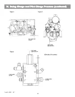
FIGURE 6
Form No. 29623
XL 5200 HYDRAULIC PRESSURE
SETTING MANUAL
5
1.
1.
1.
1.
1.
2.
2.
2.
2.
2.
3.
3.
3.
3.
3.
4.
4.
4.
4.
4.
5.
5.
5.
5.
5.
6.
6.
6.
6.
6.
Summary of Contents for XL4000
Page 2: ......
Page 73: ......
Page 76: ... 5MP ...
Page 145: ......
Page 146: ......
Page 160: ......
Page 161: ......
Page 162: ......
Page 175: ......
Page 176: ......
Page 177: ......
Page 178: ......
Page 192: ......
Page 193: ......
Page 194: ......
Page 207: ......
Page 208: ......
Page 210: ...500P ...
Page 229: ......
Page 230: ......
Page 245: ......
Page 246: ......
Page 247: ......
Page 248: ......
Page 265: ......
Page 266: ......
Page 267: ......
Page 268: ......
Page 280: ......
Page 281: ......
Page 282: ......
Page 297: ......
Page 298: ......
Page 299: ......
Page 300: ......
Page 301: ......
Page 302: ......
Page 303: ......
Page 304: ......

