Part No. 2460-4164
5.0 C
ENTER
P
IN
R
EMOVAL
Note!
The center pin assembly is held
in place by 4 bolts (5/8" standard
thread). Each bolt is equipped
with a lock nut to prevent it from
working loose during normal op-
erations.
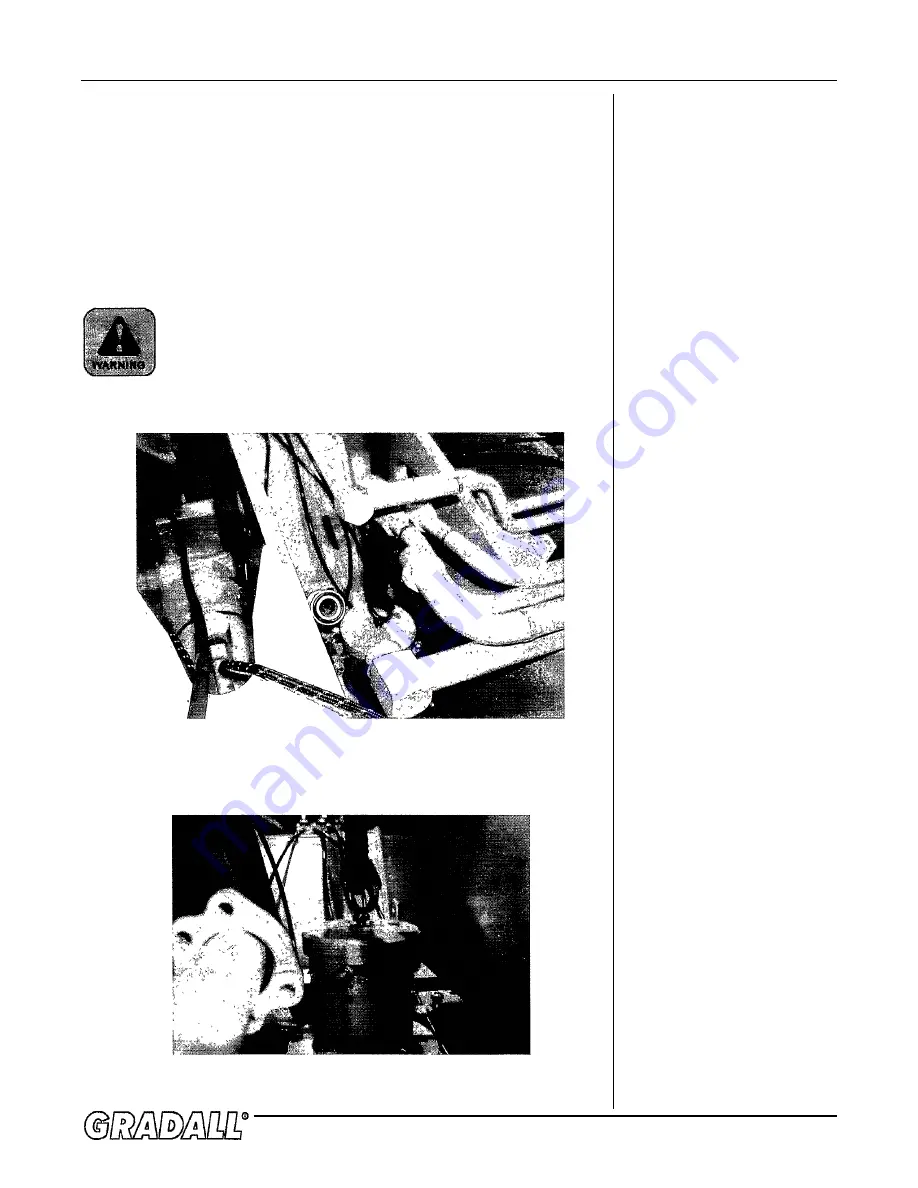
Remove the top cap, allowing the stabilizer bar to be removed. At this
point, a lifting device capable of lifting 300 lbs. may be attached to
the top of the center pin assembly. There is a threaded hole in the
middle of the pin post which accepts a lifting eye. With the lifting
device in place to support the weight, unbolt the center pin assembly
from its mounts. The assembly may now be removed, but you will have
to turn it as you withdraw it through the top. Once you have cleared
the boom cradle area, set the assembly on an appropriate work bench
where it may be cleaned and prepared for disassembly.
During these operations, make sure that you are not
lifting the assembly over anyone’s head!
Summary of Contents for XL4000
Page 2: ......
Page 73: ......
Page 76: ... 5MP ...
Page 145: ......
Page 146: ......
Page 160: ......
Page 161: ......
Page 162: ......
Page 175: ......
Page 176: ......
Page 177: ......
Page 178: ......
Page 192: ......
Page 193: ......
Page 194: ......
Page 207: ......
Page 208: ......
Page 210: ...500P ...
Page 229: ......
Page 230: ......
Page 245: ......
Page 246: ......
Page 247: ......
Page 248: ......
Page 265: ......
Page 266: ......
Page 267: ......
Page 268: ......
Page 280: ......
Page 281: ......
Page 282: ......
Page 297: ......
Page 298: ......
Page 299: ......
Page 300: ......
Page 301: ......
Page 302: ......
Page 303: ......
Page 304: ......


