Form No. 29703
XL 4100/XL 5100 HYDRAULIC SYSTEM OPERATIONS MANUAL
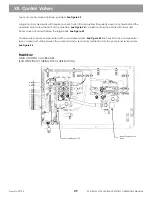
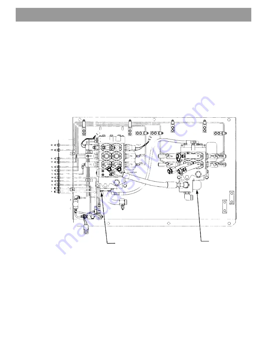
Two main control valve banks are provided.
See Figure 42
A large control valve bank with diverter, bucket, hoist, tilt (and auxiliary if required) valves is located behind the
operators cab, facing the front of the machine.
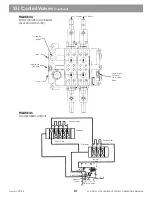
See Figure 44
A smaller control valve bank with travel and
boom valves is located behind the large bank.
See Figure 45
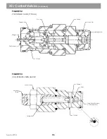
All valves are pressure compensated with a load sense system.
See Figure 45
Each section has a compensator
spool, a primary shuttle between the work ports and a secondary shuttle tied into the pump load sense system.
See Figure 46
FIGURE 42
MAIN CONTROL VALVE BANKS
(SHOWN WITHOUT TUBING FOR CLARIFICATION)
XII. Control Valves
Boom/Propel Valve
Bank
Hoist/Bucket/Tilt
39
Summary of Contents for XL4000
Page 2: ......
Page 73: ......
Page 76: ... 5MP ...
Page 145: ......
Page 146: ......
Page 160: ......
Page 161: ......
Page 162: ......
Page 175: ......
Page 176: ......
Page 177: ......
Page 178: ......
Page 192: ......
Page 193: ......
Page 194: ......
Page 207: ......
Page 208: ......
Page 210: ...500P ...
Page 229: ......
Page 230: ......
Page 245: ......
Page 246: ......
Page 247: ......
Page 248: ......
Page 265: ......
Page 266: ......
Page 267: ......
Page 268: ......
Page 280: ......
Page 281: ......
Page 282: ......
Page 297: ......
Page 298: ......
Page 299: ......
Page 300: ......
Page 301: ......
Page 302: ......
Page 303: ......
Page 304: ......


