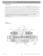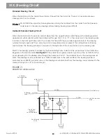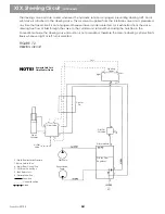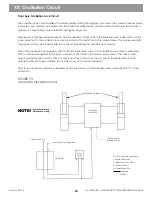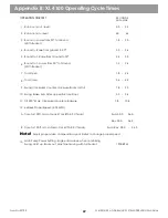
FIGURE 74
AUXILIARY CIRCUIT
The auxiliary valve has two port reliefs and a section compensator.
See Figure 75
It also has electrically
triggered end caps for spool shift. Stroke limiters on the end caps control maximum fluid flow. On/off solenoids
on each end cap receive pilot fluid from the pilot feed line and the end cover of the control valve assembly. The
reservoir return for the end caps and solenoid is also through the control valve end cover. When the front end
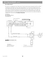
cap solenoid is energized, the solenoid opens to direct pilot fluid to the front end cap. Fluid will flow from the
front port. When the auxiliary switch (located on the left-hand joystick or on the cab floor, depending on the
machines auxiliary control configuration) is actuated, an electrical signal shifts the solenoid spool. The pilot
signal from the solenoid shifts the valve spool and the compensator meters fluid to the spool. The spool then
routes fluid to the auxiliary hydraulic function. The valve load sense system controls the compensator shift and
signals the pump load sense system.
Auxiliary speed is controlled by the stroke limiter in the end cap. The stroke limiter is set to limit maximum flow
out of the work port. When the circuit is stalled while using auxiliary hydraulics, relief valves open to protect the
circuit from excessive pressure. The valve spool allows a maximum flow rate of 40 GPM out of both work ports.
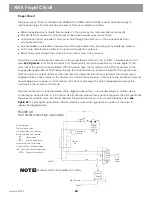
Fluid is routed to the end of the boom through a hose trough. This trough consists of guide plates, a roller,
springs and a carriage; it is located at the rear of the main boom. Normally, two hoses are in this trough. If
optional auxiliary hydraulics are installed, there are four hoses. Lubricating these hoses and guides with a dry
lubricant can extend hose life.
Always refer to instructions for the auxiliary attachments maximum flow rate and maximum working
pressure. If instructions are unclear, contact the attachment manufacturer for more information.
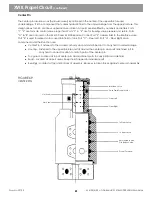
Ouick disconnects at the end of the boom make changing hydraulic attachments easy. When attachments are
not in use, their hoses are unplugged from the auxiliary circuit, rendering the circuit idle. Typical attachments
used on the end of a GRADALL boom requiring auxiliary hydraulics include: hammers, compactors, mower/brush
cutters, augers and blenders.
XXI. Auxiliary Circuit Optional
NOTE!
Form No. 29703
66
To Auxiliary Implement
To Auxiliary Implement
Electric
Solenoid
Auxillary
Control
Valve
Main Pump
Electric
Solenoid
Joy
stick
L.H.
Pilot Pressure
Right
Left
Hydraulic Fluid Path
Simplified for Clarity
NOTE!
NOTE!
Electric switch on top of
L.H. joystick. Some aux.
attachments mount
switch on cob floor.
Summary of Contents for XL4000
Page 2: ......
Page 73: ......
Page 76: ... 5MP ...
Page 145: ......
Page 146: ......
Page 160: ......
Page 161: ......
Page 162: ......
Page 175: ......
Page 176: ......
Page 177: ......
Page 178: ......
Page 192: ......
Page 193: ......
Page 194: ......
Page 207: ......
Page 208: ......
Page 210: ...500P ...
Page 229: ......
Page 230: ......
Page 245: ......
Page 246: ......
Page 247: ......
Page 248: ......
Page 265: ......
Page 266: ......
Page 267: ......
Page 268: ......
Page 280: ......
Page 281: ......
Page 282: ......
Page 297: ......
Page 298: ......
Page 299: ......
Page 300: ......
Page 301: ......
Page 302: ......
Page 303: ......
Page 304: ......


