VIII. Swing Pump
This variable displacement pump/fixed displacement motor provides independent swing function. Separate from the
main hydraulic pump, the swing pump is a variable displacement, overcenter, inline piston pump. It is attached to
the main pump case at the PTO drive (which drives the input shaft of the swing pump). The input shaft of the swing
pump drives the pump rotary group and swing charge pump and has a thru-drive for auxiliary drive at the rear of
the swing pump.
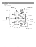
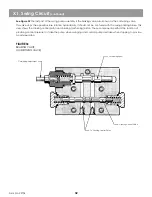
See Figure 15
The swing pump case is filled with hydraulic fluid for lubrication and cooling. When the system is exposed to a
vacuum, the hydraulic fluid changed, or a pump is removed or changed, the pump housing must be completely
filled with clean hydraulic fluid and air purged before startup.
The rotary groups in the main pump swivel from 0 (at minimum stroke to +/-15) at maximum stroke. Swivel angles
depend upon system flow and pressure requirements. Pump control settings determine swivel angles.
A small gear pump within the swing pump provides charge fluid for the swing circuit. This fluid is used to stroke the
pump and provide make-up and lubricating fluid for the pump and motor. Charge pump supply fluid comes from
the suction filter mounted in the engine compartment. Charge pressure is handled by a separate shim-type relief in
the pump case.
Swing pump controls are mounted on the pump case. Two separate valve assemblies are bolted to the pump case.
The torque control valve receives signals from the pump output ports and the swing joystick. Displacement of the
swing pump is determined by the machine controls and pressure within the swing circuit.
Maximum swing torque (pressure) is controlled by a relief located to the front and center of the swing torque
control. Swing cushioning is controlled by an adjustment screw mounted on the outside of the rear torque control
valve on the swing pump. Swing begin point is adjusted on the front torque control valve. Begin point adjustment
screws are mounted on the inside and outside of the valve. Two high pressure reliefs are provided for the pump
outlet ports to protect the pump and motor from pressure spikes. These reliefs are set above maximum swing torque
(pressure). A separate relief is provided for pump charge pressure.
See Figure 15
FIGURE 15
SWING PUMP (CROSS SECTION VIEW)
XL 4200/XL 5200 HYDRAULIC SYTEM OPERATIONS MANUAL
Form No. 29704
19
Stroking Positions
Pin-Stroking Piston
to Swashplate
Driveshaft
SealCage
Pump Case
High Pressure
Anti-Cavitation Relief
Torque
Control/Brake
Valve
Rotary Group
Port Block
Charge Relief
Charge
Pump
Thru-Drive
Piston
Summary of Contents for XL4000
Page 2: ......
Page 73: ......
Page 76: ... 5MP ...
Page 145: ......
Page 146: ......
Page 160: ......
Page 161: ......
Page 162: ......
Page 175: ......
Page 176: ......
Page 177: ......
Page 178: ......
Page 192: ......
Page 193: ......
Page 194: ......
Page 207: ......
Page 208: ......
Page 210: ...500P ...
Page 229: ......
Page 230: ......
Page 245: ......
Page 246: ......
Page 247: ......
Page 248: ......
Page 265: ......
Page 266: ......
Page 267: ......
Page 268: ......
Page 280: ......
Page 281: ......
Page 282: ......
Page 297: ......
Page 298: ......
Page 299: ......
Page 300: ......
Page 301: ......
Page 302: ......
Page 303: ......
Page 304: ......


