background image

26

USER GUIDE

FITTING RACKMOUNT EARS

Summary of Contents for SoundCraft E8

Page 1: ...Soundcraft E8 Mixer ...

Page 2: ......

Page 3: ...1 SAFETY GUIDE Page Safety Symbol Guide 2 Approvals and Notice 3 Warranty 4 Important Safety Instructions 5 Cautions 5 Warnings 6 ...

Page 4: ...of the warranty all text marked with these symbols should be read carefully CAUTIONS Must be followed carefully to avoid bodily injury WARNINGS Must be observed to avoid damage to your equipment NOTES Contain important information and useful tips on the operation of your equipment ...

Page 5: ... a com mitment on the part of the vendor Soundcraft shall not be liable for any loss or damage whatsoever arising from the use of information or any error contained in this manual No part of this manual may be reproduced stored in a retrieval system or transmit ted in any form or by any means electronic electrical mechanical optical chemi cal including photocopying and recording for any purpose wi...

Page 6: ...both to and from the Dealer or Soundcraft and postage must be prepaid 4 This warranty shall only be valid if a the Equipment has been properly installed in accordance with instructions contained in Soundcraft s manual and b the End User has notified Soundcraft or the Dealer within 14 days of the defect appearing and c no persons other than authorised representatives of Soundcraft or the Dealer hav...

Page 7: ...was purchased THIS UNIT MUST BE EARTHED Under no circumstances should the mains earth be disconnected from the mains lead ATTENTION Cet appareil doit être branché à la terre The wires in the mains lead are coloured in accordance with the following code Replacement Part No FJ8016 UK FJ8017 EU FJ8018 US CAN UK EU US CAN Earth Ground Green and Yellow Green and Yellow Neutral Blue White Live Brown Bla...

Page 8: ...riods of time Refer all servicing to qualified service personnel Servicing is required when the appa ratus has been damaged in any way such as power supply cord or plug is damaged liquid has been spilled or objects have fallen into the apparatus the apparatus has been exposed to rain or moisture does not operate normally or has been dropped It is recommended that all maintenance and service on the...

Page 9: ...aster Section 22 Using Your Spirit ES Console 24 Fitting Rackmount Ears 26 Application 1 Live Sound Reinforcement 27 Application 2 Broadcast 28 Application 3 Recording 28 Application 4 Keyboard SubMixer 29 Application 5 Linking Two Spirit ES Consoles 29 Glossary 30 Typical Specifications 32 Dimensions 34 System Block Diagram 35 Typical Connecting Leads 36 Control Position Markup Sheet 38 CONTENTS ...

Page 10: ...ast as possible this manual begins with a 10 second tutorial Here you can find quick information on any feature of the console and a page reference where you can find a more detailed explanation 1 t 2 3 4 5 6 7 8 9 p y d 0 q u i g h f s e w o a r ...

Page 11: ...n path comes back in on the ring of the jack plug rMONITOR O Ps Jack These are used to feed your monitoring system This can be directly connected to powered monitors or indirectly via an amplifier to standard monitors t MASTER FADERS These faders control the overall level of the mix bus yMAIN METERS These show the level of the mix outputs When the SOLO LED is lit the meters show the level of the s...

Page 12: ...in the Spirit E Series bringing you the great Soundcraft quality in a small format console without compromise You will also be glad to know you have a one year warranty with your product from the date of purchase The Spirit E Series has been designed using the latest high end software based engineering packages Every console from Soundcraft has been proven to stand up to all the stress and rigours...

Page 13: ...stem with care and do not share sockets or earthing with lighting dimmers Position the mixer where the sound can be heard clearly Run audio cables separately from dimmer wiring using balanced lines wherever possi ble If necessary cross audio and lighting cables at right angles to minimise the pos sibility of interference Keep unbalanced cabling as short as possible Check your cables regularly and ...

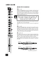
Page 14: ...sources by wiring up the jacks as shown although you should then keep cable lengths as short as possible to minimise interference pick up on the cable Note that the ring must be grounded if the source is unbalanced Set the input level using the GAIN knob starting with the knob turned fully anticlockwise Unplug any MIC connection when using the LINE input Insert Point The unbalanced pre EQ insert p...

Page 15: ...ed to both paths by plugging into the Left jack only NB Channels 3 6 have a dedicated mono switch to perform this function Mix Inserts The unbalanced pre fade Mix insert point is a break in the output signal path to allow the connection of for example a compressor limiter or graphic equaliser The Insert is a 3 pole A gauge jack socket which is normally bypassed When a jack is inserted the signal p...

Page 16: ...bles have their screens connected to ground In some unusual circumstances to avoid earth or ground loops ensure that all cable screens and other signal earths are connected to ground only at their source and not at both ends If the use of unbalanced connections is unavoidable you can minimise noise by following these wiring guidelines On INPUTS unbalance at the source and use a twin screened cable...

Page 17: ... Master section Compare a suspect channel with an adjacent channel which has been set up identically Use SOLO to monitor the signal in each section Insert contact problems may be checked by using an insert bypass jack with tip and ring shorted together as shown below If the signal appears when the jack is inserted it shows that there is a problem with the normalling contacts on the jack socket cau...

Page 18: ...ars The input is BALANCED for low noise and top quality from professional equipment but you can use UNBALANCED sources by wiring up the jacks as shown below although you should then keep cable lengths as short as possible Unplug anything in the MIC input if you want to use this socket Set the input level using the GAIN knob 3 Insert Point The unbalanced pre EQ insert point is a break in the channe...

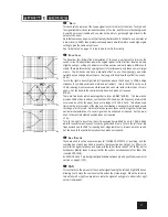
Page 19: ... two knobs which work together to form a SWEPT MID EQ The lower knob provides 15dB of boost and cut just like the HF EQ knob but the frequency at which this occurs can be set by the upper knob over a range of 140Hz to 3kHz This allows some truly creative improvement of the signal in live situations because this mid band covers the range of most vocals Listen carefully as you use these controls tog...

Page 20: ...itial Setup section on page 23 for help in setting a suitable signal level 0 SOLO When the latching SOLO switch is pressed the pre fade pre mute signal is fed to the headphones control room output and meters where it replaces the MIX The SOLO LED on the Master section illuminates to warn that a SOLO is active This is a useful way of listening to any required input signal without interrupting the m...

Page 21: ...level inputs All the RCA phono connectors are UNBALANCED 3 pole A gauge TRS sockets These inputs accept 3 pole A gauge TRS jacks Use these inputs for sources such as keyboards drum machines synths tape machines or processing units The inputs are BALANCED for low noise and top quality from professional equipment but you can use UNBALANCED sources by wiring up the jacks as shown in the Wiring it Up ...

Page 22: ...d Set the knob to the centre detented position when not required The con trol has a shelving response giving 15dB of boost or cut at 180Hz 5 AUX SENDS These are used to set up a separate mixes for FOLDBACK EFFECTS or recording and the combination of each Aux Send is mixed to the respective Aux Output at the rear of the mixer For Effects it is useful for the signal to fade up and down with the fade...

Page 23: ...l 9SOLO When the latching SOLO switch is pressed the pre fade pre mute signal is fed in mono to the headphones control room output and meters where it replaces the MIX The SOLO LED on the Master section illuminates to warn that a SOLO is active The Left and Right meters display the SOLO signal in mono This is a useful way of listening to any required input signal without interrupting the main mix ...

Page 24: ...k if the input GAIN settings have been correctly set to give maximum travel on the faders for smoothest control 4 MIX OUTPUTS INSERTS The Mix LEFT and RIGHT outputs are sent from the XLR sockets as balanced signals The Mix INSERT points are on 3 pole A gauge jacks and are unbalanced 5 BARGRAPH METERS The three colour peak reading BARGRAPH METERS normally show the level of the MIX RIGHT and MIX LEF...

Page 25: ...ne level will track the Monitor Level q MONITOR OUTPUTS The Monitor Outputs are on 3 pole A gauge jacks and are balanced connections w PHONES LEVEL This control sets the output level to the Headphone outputs If headphones are plugged into the PHONES jack then the knob sets a comfortable headphone listening level without affecting the Monitor output levels e HEADPHONES JACK The PHONES output is a 3...

Page 26: ...d the position that gives the desired effect is the correct position INITIAL SETUP Once you have connected up your system see the sections on connection and wiring earlier in this manual for guidance you are ready to set initial positions for the controls on your mixer Set up individual input channel as follows Connect your sources microphone keyboard etc to the required inputs WARNING Phantom pow...

Page 27: ...tput level Note The level of any source signal in the final output is affected by many factors princi pally the Input Gain control Channel Fader and Mix Faders You should try to use only as much microphone gain as required to achieve a good balance between signals with the faders set as described above If the input gain is set too high the channel fader will need to be pulled down too far in compe...

Page 28: ...26 USER GUIDE FITTING RACKMOUNT EARS ...

Page 29: ... APPLICATIONS APPLICATION 1 LIVE SOUND REINFORCEMENT Using Delay in REINFORCEMENT SYS TEMS The drawing below illustrates how to calculate delay settings for fill speakers in multiple speaker installations ...

Page 30: ...28 USER GUIDE APPLICATION 2 BROADCAST APPLICATION 3 RECORDING ...

Page 31: ...29 APPLICATION 4 KEYBOARD SUBMIXER APPLICATION 5 LINKING TWO SPIRIT ES CONSOLES ...

Page 32: ...t allows the boosting or cutting of selected bands of frequencies in the signal path fader a linear control providing level adjustment feedback the howling sound caused by bringing a microphone too close to a loudspeaker driven from its amplified signal foldback a feed sent back to the artistes via loudspeakers or headphones to enable them to monitor the sounds they are producing frequency respons...

Page 33: ...er fader and therefore affected by fader position pre fade the point in the signal path before the monitor or master fader position and therefore unaffected by the fader position rolloff a fall in gain at the extremes of the frequency response shelving an equaliser response affecting all frequencies above or below the break frequency i e a highpass or lowpass derived response spill acoustic interf...

Page 34: ...ine input to any output 0 5dB 20Hz 20kHz THD Noise Mic gain 30dB 30dBu input Mix out fader max 1kHz 0 007 Input output Impedances Mic input 2 4kW Line input 11kW Stereo input 100kW Outputs 75W Input output levels Mic input max level 17dBu Line input max level 30dBu Stereo input max level 30dBu Mix output max level 20dBu Headphones 200W 300mW EQ EQ Bands Mono input 15dB Lo 80Hz Mid swept 140Hz 3kHz...

Page 35: ...33 WEIGHT ES 7 75 kg 17 09 lbs AVERAGE POWER CONSUMPTION QUIESCENT ES 15 5 Watts MIN MAX OPERATING TEMPERATURE E SERIES FAMILY Centigrade Farenheit 0 C 50 C 32 F 122 F ...

Page 36: ...34 USER GUIDE ES Dimensions ...

Page 37: ...35 SYSTEM BLOCK DIAGRAM ...

Page 38: ...36 USER GUIDE TYPICAL CONNECTING LEADS ...

Page 39: ...37 ...

Page 40: ...R GUIDE CONTROL POSITION MARK UP SHEET To assist you in restoring the console to a previous setting you may copy this sheet as many times as you like and use the copies to make a note of your control settings ...

Page 41: ......

Page 42: ...d The Power House Elstree Film Studios Shenley Road Borehamwood WD6 1JG Phone 020 8324 2100 FAX 020 8324 2933 email office gradav co uk Web www gradav co uk See our catalogue for details of these and more Dirty Rigger products ...

Reviews: