10. Alarm indicator contact
Before opening the equipment pull the plug out from the mains socket!
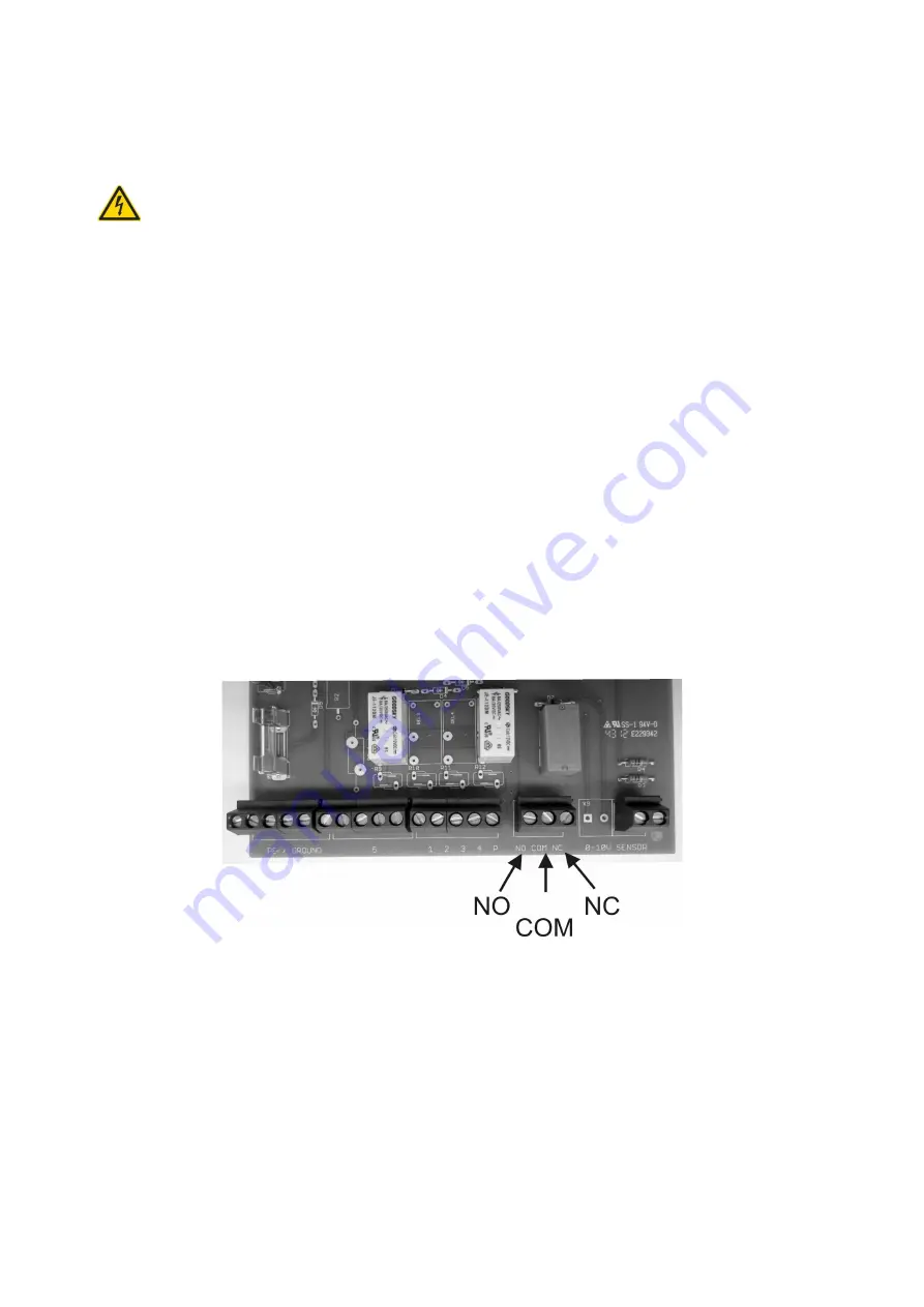
As an additional function, your unit is equipted with a potential-free alarm indicator contact.
This contact is designed as a changeover contact element. A maximum of 230V AC is ap-
proved when a current of 1A is switched. The activation of this contact occurs as soon as
one of the malfunctions listed under point 6 appears.
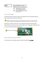
The following picture shows the location of the connections. They become available as
soon as the lower cover of the system control unit is opened (see diagram 1 ).
Explanation of terms:
–
COM is the common port
–
NC is coupled to the COM port when there is no current
–
NO is connected to the COM port when there is a malefunction
22
Picture 16: Location of the fault indicator
Summary of Contents for 351021
Page 27: ...Space for your notes 27 ...

