4. Assembly and installation
12 / 28
4.
Assembly and installation
Take the EcoSmart and accessories out of the transport packaging. Immediately check the entire system
for any damage. Damage must be reported before assembly.
4.1
Wall mounting
The system is designed to be mounted (above backpressure level) in a frost-proof, flood-protected and
dry area.
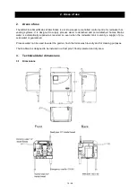
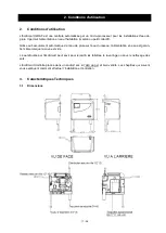
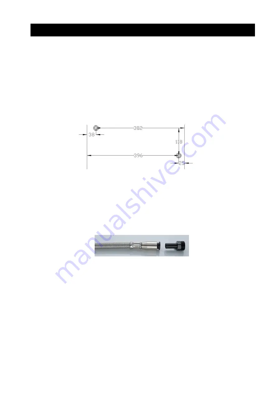
Mark the drilling points on the desired wall as shown in the diagram below and drill with a 10mm bit. The
console can then be mounted on the wall.
4.2
Emergency overflow connection
The emergency overflow is constructed with standard DN 40 pipes. In rooms with a floor drain it is suffi-
cient to allow overflowing water to flow out of the feed unit without a connection to the sewer system be-
cause water does not escape during normal operation. If there is no floor drain the emergency overflow is
connected to the waste water network.
4.3
Mains water connection
Use the ¾“ reinforced hose supplied to connect the float valve to the mains water network. The reinforced
hose is connected first to the mains water pipe and then to the quick-release fastening on the feed box.
An additional shutoff valve makes future maintenance easier.
The mains water pipe must be flushed through thoroughly before installation. A fine filter installed on site
will guarantee the long-term function of the float valve and 3-way changeover valve.
4.4
Suction pipe connection
The suction pipe is routed to the installation site of the mains water intake inside an empty pipe, always
rising, without bends. The suction element must be fitted with a filter strainer to protect the system from
contamination.
The connection to the feed unit is made at the 3-way changeover valve on the 90° bend using the rein-
forced hose with quick-release fastening supplied.
Summary of Contents for ECO SMART
Page 31: ...Notizen Notes Notas ...
Page 32: ......


