6
.
Assembling the interior switch cabinet
55
/
144
6.
Assembling the interior switch cabinet
6.1
Selecting the location
When selecting the location for the switch cabinet, the following must be taken into consideration:
•
The switch cabinet must be mounted above the highest water level in the tank in order to
avoid overflows and water intake in the open channel in the event of an accident.
•
The system generates noise! When operating, the air compressor generates continuous
noise comparable to a freezer.
•
The machine cabinet requires a separately protected electrical connection (16 amp, slow
blow). The electrical connection serves as a mains disconnecting device and must be easily
accessible at all times. Additional electrical fixtures on the same fuse may disrupt operation.
•
The location of the machine cabinet must be a dry, cool and well-ventilated room. The cabi-
net, in particular the ventilation openings and the circuit breaker, must not be covered and
must be freely accessible for maintenance work.
•
The air hoses must be no longer than 20 metres.
6.2
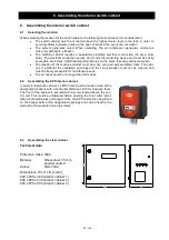
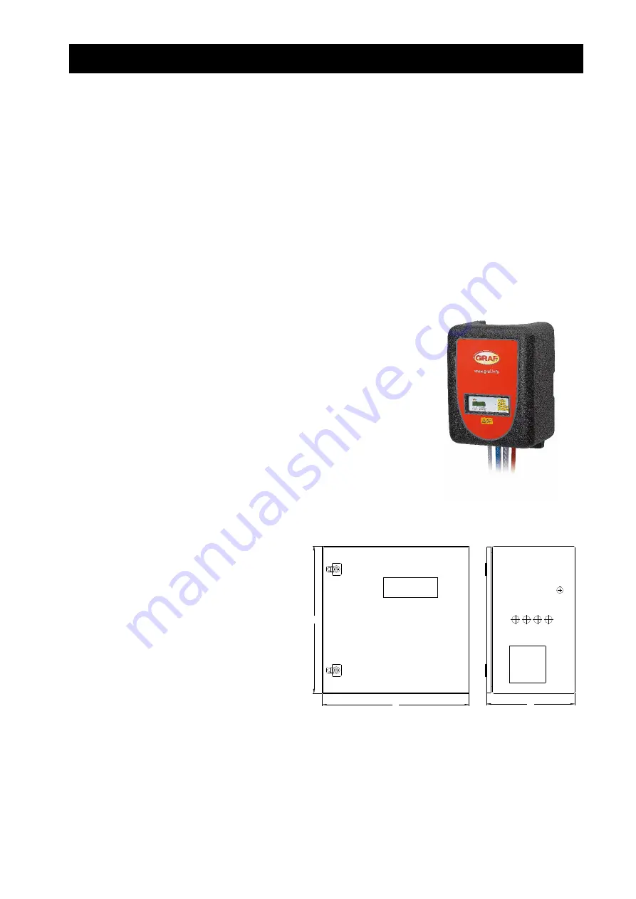
Assembling the EPP interior cabinet
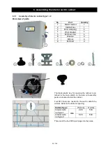
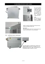
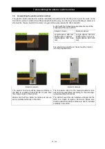
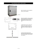
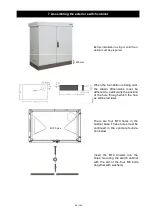
In order to fasten the cabinet, 2x M10 holes must be made on-site at the
designated locations with a horizontal distance of 28 cm between them.
The front of the cabinet is secured with a screw located above the con-
trol unit. This must be unfastened before opening the front. After instal-
lation of the wall plugs and hanger bolts, the EPP cabinet can be placed
on the hanger bolts at the designated openings and can be fixed to the
wall using the washers and wing screws.
6.3
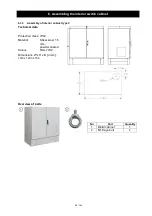
Assembling the steel cabinet
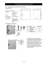
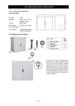
Technical data
Protection class:
IP44
Material:
Sheet steel 1.5 mm,
powder coated
Colour:
RAL 7032
Dimensions W x H x D [n mm]:
500 x 500 x 300 (interior cabinet 1)
600 x 600 x 330 (interior cabinet 2)
800 x 675 x 500 (interior cabinet 3)
B
H
T

