7 / 18
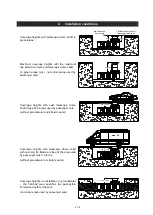
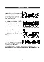
Subsoil
Telescopic dome shaft
Compacted foundation refer page 2.
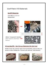
Backfill Material, 7mm Minus or washed sand
fill material must be porous see page 2.
Covering layer
PLATIN Rainwater Underground Tank
Concrete layer for surfaces used by passenger
cars
ß
--> angle of cut to depth of the trench
5.1
Construction site pre-check
The following points should be clarified before installation commences:
• The structural suitability of the ground (geotechnical report recommended)*
• Maximum groundwater levels which occur and drainage capability of the subsoil
• Types of load expected, for example: traffic loads
• Location of all underground services
* A geotechnical report conducted by civil testing engineers is strongly recommended to
determine the physical characteristics of the subsoil before installation/excavation commences.
For setback distance from neighbouring boundary and any buildings, please contact local council.
5.2
Trench
To ensure that sufficient space is available for working, the base area of the trench must exceed the
dimensions of the tank by > 100 mm on each side; the distance from solid constructions must be more
than the depth of the trench away from the structure.
If the depth of the trench is > 1250 mm an embankment must be designed according to meet all safety
standards. The construction site must be level and must guarantee sufficient load-bearing capacity.
The depth of the trench must be sized, so that the maximum earth coverage (see point 2
– installation
conditions) above the tank is not exceeded.
A layer of compacted, Type B Crushed Rock (porous round-grain gravel grain size 8/16, thickness
approx. 100 - 150 mm) is applied as the foundation. . See Page 2.
5.
Installation and assembly
ß
< 300 mm
< 300 mm
< 300 mm
< 300 mm
> 100 mm
ß
--> DIN 4124
6
3
1
4
2
5
> 100 mm
7


