background image

Error message


Error message description


Is displayed...


Action


Confirmation/Reset


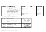
E.20


Clock Input Signal Missing


This error message appears when the clock input 

signal is missing or the Clock Signal Input 

Frequency is below 0.5Hz while the Clock 
Operating Mode is enabled at Clock Operating 
Mode 2 or 3 and the pump is started.


As long as the Error is 
persistent and the System 
gets an external Run Signal.


No action


MODE or I/O Button 
when there is no 
external Run Signal or 
when the Error 
disappear by itself


E.21


Maximum Clock Signal Input Frequency Exceeded


The maximum allowable Clock Signal Input 
Frequency in Clock Input Operation Mode 2 or 3 

exceeds over ist computable range. In this case, 

the Clock Signal Input Frequency is clamped at its 
maximum limit. The range maximum limit is 
1000Hz.


As long as the Error is 

persistent and the System 

gets an external Run Signal.


No action


No confirmation 
possible


E.30


Maximum Feeding Quantity Exceeded


This error message appears when the motor 
rotational speed is too high so that the motor may 
not be able to keep track on this speed without 
losing steps.


As long as the Error is 
persistent and the System 
gets an external Run Signal.


No action


No confirmation 
possible


E.40


Fluid Motion Controller Flow Error


The Fluid Motion Controller has detected a 
lubricant flow error.


Once the Error has occurred


Machine disabled


MODE or I/O Button


E.41


Pump Head Missing Error


The Pump has been started without a proper Pum 

Head attached to the system


As long as the Error is 
persistent and the System 

gets an external Run Signal.


Machine disabled


MODE or I/O Button 
when there is no 

external Run Signal


E.42


Pump Head Fluid Motion Sensor Error


The Pump Head's Fluid Motion Sensor is faulty or 
the wiring to the Sensor is broken


As long as the Error is 
persistent and the System 
gets an external Run Signal.


Machine disabled


MODE or I/O Button 
when there is no 
external Run Signal


        Instruction Manual GRAF SINGLE LUB 2  / Version 4.0 

 05.2020 


 19 

Summary of Contents for SINGLE LUB 2

Page 1: ...INSTRUCTION MANUAL SINGLE LUB 2 Graf Chemicals GmbH Phone 49 0 8041 79285 16 Prof Max Lange Platz 4 frank engelbrecht graf chemicals com 83646 Bad Tölz Germany www graf chemicals com ...

Page 2: ...E LUB 2 Version 4 0 05 2020 2 CONTENTS 1 GRAF Single Lub etti g The co figuratio e u Error essages 5 Technical data 6 Complete o er ie Error essages 7 Diagram electrical installation on winding machines EC Declaratio of Co for ity ...

Page 3: ...Front side Status LED Input LED display Window for visual operation check Magnet sensor keys A B C Seal rubber Sponge type 1 2 Lubricant injection Open Close Instruction Manual GRAF SINGLE LUB 2 Version 4 0 05 2020 3 ...

Page 4: ...nding machine Connector cable to applicator Pump output 1 8 tube connection Lubricant input 1 8 tube connection Pump input 1 8 tube connection Connector cable to dosing unit Instruction Manual GRAF SINGLE LUB 2 Version 4 0 05 2020 4 ...

Page 5: ...de Press the letter a i the a e graf Press key for 6 seconds Key is only active when pump is not running green LED A must be off 1 2 3 Keys 1 2 3 to set numbers A short press on key increases number by one Description of magnet sensor keys input keys A Green LED lights up when product is being metered B Yellow LED lights up when applicator is below operating temperature lower than 90 of pre set te...

Page 6: ...the dosing unit please use the following formula lub min min activity uptake g m eff Nm m d threadspee g Setting With Thread speed winding speed Uptake quantity of lubricant to be applied to the yarn in of yarn weight Nm the weight of the yarn how many meters of yarn per one 1 gram Lub activity the of active material solid matter in the lubricant min m g m eff Calculation example Thread speed 1200...

Page 7: ...time 2 4 Turn on off With the I O key the pump can be turned off The display indicates The luminous decimal point of the second digit indicates that the pump is in off mode and will not meter even if the winding machine is working By another press on the I O key the pump is changed to on mode and the display shows the value which was indicated before The applicator is still hot 2 5 Applicator Temp...

Page 8: ...f any parameter may lead to a malfunction of the device To enter the configuration menu the MODE key must be pressed for 3 sec After the last menu item has been passed the configuration menu is left automatically To leave the configuration menu prematurely the I O key must be pressed Changed parameters are automatically saved The configuration menu is passed through in the following order Applicat...

Page 9: ... Default value F 65 MODE The red LED C lights up when the reaction point has been reached For test purposes the moment the parameter F is entered the flow motion sensor starts to detect if lubricant is flowing through the pump As the motor is not running and no lubricant is moving in this mode the flow motion sensor should show an error after approx 1 minute The red LED C indicates the error With ...

Page 10: ... standstill can be specified in 6 steps Ad 0 No delay immediate temperature reduction at standstill Ad 1 temperature reduction 10 seconds after standstill Ad 2 temperature reduction 30 seconds after standstill Ad 3 temperature reduction 1 minute after standstill Ad 4 temperature reduction 2 minutes after standstill Ad 5 temperature reduction 5 minutes after standstill Ad 6 temperature reduction 10...

Page 11: ...k drop detection Default value CL 0 Acceleration ramp only active with corresponding setting I O C 10 Clock input rate setting determines the clock input rate in pulses meter MODE C 01 C 50 When the system is used on a winding machine with a non constant thread speed the system must be connected to a speed signal equivalent to the thread speed The C Value must be equal to the count of pulses per m...

Page 12: ...ade and gear setting sets lub quantity decade setting MODE dP 0 d P1 d P2 dP 0 Feeding Quantity Input with 1 decade after comma e g 12 3 g min dP 1 Feeding Quantity Input with 2 decades after comma e g 1 23 g min dP 2 Feeding Quantity Input with 2 decades after comma only for use with 10 1 motor gear e g 1 23 g min Default value dP 0 I O L 20 Maximum Feeding Quantity Limitation Limits the max Adju...

Page 13: ...tarting the pump This value should be chosen according to the acceleration of the winding machine The minimum value is 0 the maximum value is 30 seconds I O d 01 Deceleration time at pump stop d 00 d 30 This setting determines the deceleration time from when the pump is stopped until the feed quantity is zero With setting d 00 the pump stops immediately after switching off Default value d 01 NOTE ...

Page 14: ...printed board has been exchanged Create new settings in the configuration menu 4 3 Failure of applicator only with hot application The applicator has not reached the working temperature NOTE This error message only appears during winding Additionally to this error message the yellow LED B lights up also when the winding machine has already been stopped The error message is automatically cancelled ...

Page 15: ...k connector The wheel of the speed sensor or the device is defective Exchange the wheel or the device and send in the part for repair 4 5 Breakdown of output overtaxing NOTE This fault can only appear when output and yarn speed are coupled The clock signal of the winding machine is missing The output capacity of the pump has been exceeded Possible cause Remedial measures The output has been set to...

Page 16: ...pplicator or the pump is blocked Clean applicator or pump The output has been adjusted to the value 00 3 g min Check the output setting The sensitivity of the flow motion sensor has been set too high Set the flow motion sensor to a lower se siti ity see test a d setting of the flo otio se sor Device is defective Exchange device and send it for repair The flow motion sensor indicates No product is ...

Page 17: ...0 C Air humidity 0 80 not condensating Electrical data Power supply 24 VDC Current consumption Off mode 1W Standby 2W Running 5W With hot applicator heating 30W With hot applicator standby 15W Dimensions approx 100 mm 100 mm 140 mm 70 mm 60 mm Instruction Manual GRAF SINGLE LUB 2 Version 4 0 05 2020 17 ...

Page 18: ...ure level above a fixed threshold of 5 degrees Celsius below the set temperature by any reason This error message is only displayed when the error persists while the pump is being started The error message can then be confirmed by the action described As long as the Error is persistent and the System gets an external Run Signal Machine disabled MODE or I O Button when there is no external Run Sign...

Page 19: ...onfirmation possible E 30 Maximum Feeding Quantity Exceeded This error message appears when the motor rotational speed is too high so that the motor may not be able to keep track on this speed without losing steps As long as the Error is persistent and the System gets an external Run Signal No action No confirmation possible E 40 Fluid Motion Controller Flow Error The Fluid Motion Controller has d...

Page 20: ...the Error has occurred No action MODE or I O Button E 51 Pump Test Feed Error The system has detected a problem during execution of the Pump Test Feed The Pump Test Feed must be repeated Once the Error has occurred No action MODE or I O Button E 60 Machine Enable Output Error The Machine Enable Output Transistor is overloaded or shorted to 24VDC Although the output transistor is properly protected...

Page 21: ...ltage of the system is above 30VDC Further increase of the Power Supply Voltage may cause the device to be damaged As long as the Error is persistent Machine disabled No confirmation possible Status LED Status LED description Is ON RED Fluid Motion Controller and Hal Sensor DIGIT Button pressed indicator As long as a Fluid Motion Controller Error E 40 E 44 is persistent While a Hal Sensor DIGIT Bu...

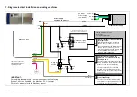
Page 22: ... stopping the Single Lub 2 Energizing the Relay R1 will start the device Relay contact 11 14 closes De energizing the Relay R1 will stop the device Relay contact 11 14 opens User proper Relais operating voltage and current type DC AC to meet the interface output capabilities OK fault Interface Input for stopping the spindle in case of fault detected by the Single Lub 2 In case of normal operation ...

Reviews: