background image

IOG 5057.20

5

This faucet complies with NSF61/9, ASME/ANSI A112.18.1

and CSA B 125 Standards.

Este grifo se encuentra conforme con losestandares de NSF61/9,

de ASME/ANSI A112.18.1 y de CSA B 125.

Installation Instructions     Instrucciones de Instalación

 LAVATORY FAUCET

GRIFO DE LAVATORIO

3.9

3.10

3.8

K2

9

10

3

11


13-3/4” (350mm)

13-3/4” (350mm)

See 

fig. 

4

ENGLISH

1.

2.

Ver. 

fig. 

1.

2.

ESPANOL

~

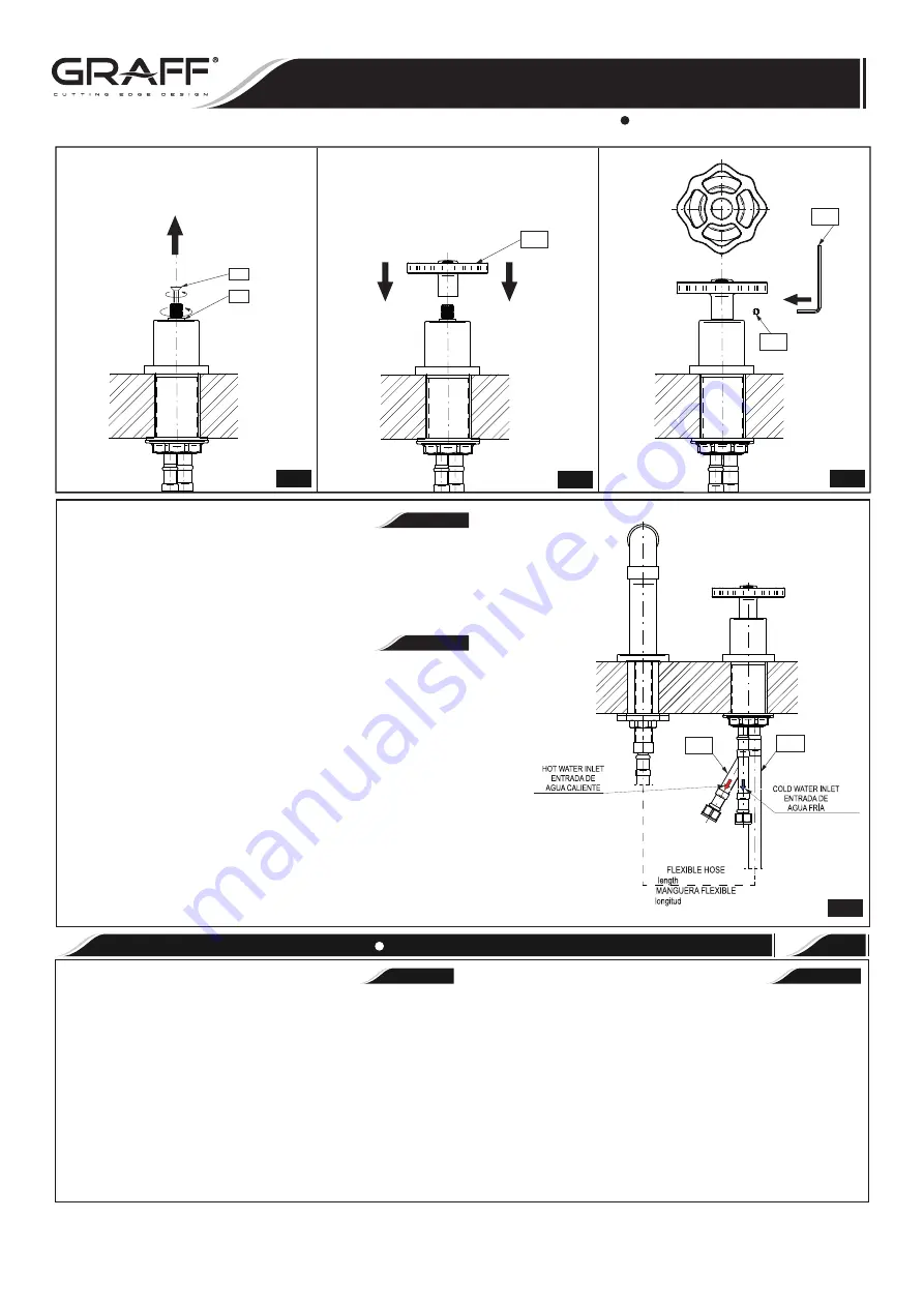
Install  the  13-3/4” (350mm) 

flexible

  hose  

(7)

 as  shown  in  

fig.

  4.  

Connect 

flexible

 hoses 

(8)

 to the inlet valves of water supply lines. Be 

sure to hold the 

flexible

 hoses in place when tightening the nut so as 

not twist the hoses. Use adjustable wrench when tightening. Do not 

overtighten.

Instale  de  la  manguera 

(7) 

de  la  longitud  de  13-3/4”  (350mm)  de  

acuerdo con el diseño 4.

Conecte las mangueras 

flexibles 

(8)

 a las líneas de fuente de entrada 

de agua. Mientras 

fijas

 la tuerca, sujeta el tubo 

flexible

 para queno se 

tuerza. Use la llave ajustable para ajustar las piezas. No ajuste dema-

siado.

4

See 

fig. 

1

1. Remove aerator insert 

(2)

 (use the special key 

)

K1

(

 supllied) and turn 

faucet handle to the full on mixed position.

2. Turn on hot and cold water supply valves and 

flush 

water lines for 15 

1)

seconds  .

3. Check all connections at arrows for leaks. Re-tighten if necessary, but 

do not overtighten.

4. Replace aerator insert 

(2)

. Use the special key 

)

K1

(

.

1)

 IMPORTANT

: This flushes aw

ay any debris that could cause damage to 

internal parts.

Ver la 

figur

a 1

1. Retire el inserto del aereador 

(2)

 (use una llave especial 

K1

(

) anexa al 

juego) y gire el mango del grifo a la posición de mezclado completo.

2. Abra las válvulas de suministro de agua fría y caliente y enjuague las 

1)

lineas de agua por 15 seg. .

3. Chequee todas las conecciones para ver si hjay fuga de agua. Reajuste 

si es necesario, pero no ajuste demasiado.

4. Coloque el inserto del aereador 

(2)

. Ajuste solo con la llave especial 

(K1)

.

1)

 IMPORTANTE: Esto limpia los residuos que podrían causar daño a las 

piezas internas con un chorro de agua.

3

AFTER INSTALLATION BEFORE USE

DESPUES DE LA INSTALACIÓN Y ANTES DEL USO


ENGLISH

~

ESPANOL

It is recommended that every 3-6 months (depending on water quality) 

you remove the aerator (item 2, 

fig. 

1) from the faucet spout 

(1) 

in order 

to remove any impurities. For this purpose, use the special key 


)

K1

(

(supplied).

Una vez a 3-6 meses (dependiendo de la calidad del agua) se recomienda 

quitar el difusor (pos. 2 dis. 1) del caño de la mezcladora 

(1)

 con el 

fin 

de 

limpiarlo de todo tipo de ensuciamiento. Para eso use una llave especial 

 )

K1

(

anexa al juego.

7

8

Rev. 4 January 2019

Summary of Contents for G-11320 Series

Page 1: ...uld have the following tools adjustable wrench adjustable pliers hex key included in the box Teflon tape Para la instalación fácil de su grifo de la GRAFF usted necesitará LEER TODAS las instrucciones completamente antes de comenzar LEER TODA la información sobre las advertencias cuidado y mantenimiento Para terminar el proyecto usted debe recolectar las herramientas y todas las piezas que usted ne...

Page 2: ...Standards Este grifo se encuentra conforme con losestandares de NSF61 9 de ASME ANSI A112 18 1 y de CSA B 125 Installation Instructions Instrucciones de Instalación LAVATORY FAUCET GRIFO DE LAVATORIO 1 1 2 3 5 4 6 7 8 9 10 12 13 14 15 16 17 18 20 21 22 19 11 K2 K1 Rev 4 January 2019 ...

Page 3: ...ESIVO SCREW TORNILLO HANDLE KNOB METAL WASHER ARANDELA DE METAL MOUNTING NUT TUERCA DE MONTAJE ESPANOL PROGRESSIVE CARTRIDGE SCREW TORNILLO NUT TUERCA HOSE M10x1 G3 8 350MM LENGTH MANGUERA M10x1 G3 8 LONGITUD DE 350MM 1 See fig 2 ENGLISH FAUCET INSTALLATION INSTALACIÓN DEL GRIFO 2 1 2 3 4 Ver fig 2 1 2 3 ESPANOL 4 Place the spout 1 and center over side hole of mounting surface From underneath the le...

Page 4: ...oscado 16 entonces atornille la tuerca de montaje 19 Apriete únicamente a mano fig 3 2 En la superficie de montaje coloque la zócalo de la palanca y cuerpo de la palanca 4 Posicione la base en relación a la brida y asegúrela con el tornillo de fijación 11 usando la llave allén adjunta K2 figs 3 3 3 4 Gire el fuso de la válvula a la izquierda alcanzando su máximo en el sentido antihorario Si es difícil...

Page 5: ...r 15 1 seconds 3 Check all connections at arrows for leaks Re tighten if necessary but do not overtighten 4 Replace aerator insert 2 Use the special key K1 1 IMPORTANT This flushes away any debris that could cause damage to internal parts Ver la figura 1 1 Retire el inserto del aereador 2 use una llave especial K1 anexa al juego y gire el mango del grifo a la posición de mezclado completo 2 Abra las...

Page 6: ...ion Care should be given to the cleaning of this product Although its finish is extremely durable it can be damaged by harsh abrasives or polish Never use abrasive cleaners acids solvents etc to clean any Graff product To clean simply wipe gently with a damp cloth and blot dry with a soft towel Warranty conditions and warranty registration card are outlined on a separate sheet Su producto de la Gr...

Reviews: