SEAT
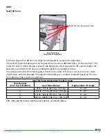
Seat Tilt Force
Seat Tilt Force
Adjustment Positions
4
3
2
1
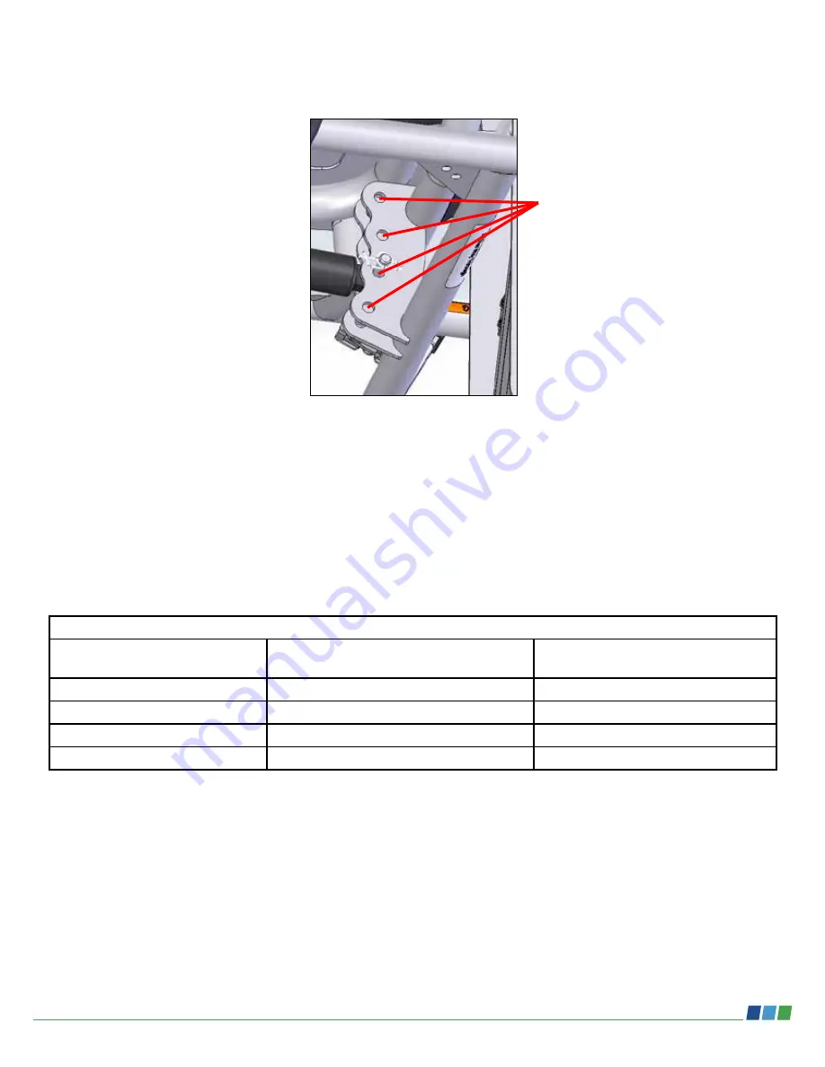
Seat Tilt Force Adjustment Holes
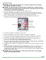
The force required to tilt the seat while the tilt handle is squeezed is adjustable.
The seat tilt piston retaining pin can be placed in one of four different holes, as shown above. The
lower the hole in which the pin is placed, the higher the effort required to tilt, and the higher the
assistance provided to the user in rotating themself to an upright position.
The ideal position for the retaining pin is based on a variety of factors such as user mass, mass
distribution, and arm strength. Though the ideal setting is a comfort judgment based on the user,
the following chart is given as guidance.
Seat Tilt Force Adjustment Position Chart
Hole Number
(from Top to Bottom)
User Mass Range
Approximate Tilt Angle
1
50 lb - 155 lb (22.7 kg - 70.3 kg)
5° - 40°
2
155 lb - 175 lb (70.3 kg - 79.4 kg)
5° - 35°
3
175 lb - 225 lb (79.4 kg - 102.1 kg)
5° - 30°
4
225 lb - 300 lb (102.1 kg - 136.1 kg)
5° - 25°
Info: The seat tilt force is factory-set in hole 3, as shown above.
20
EJ_PT3000-18-INS-LAB-RevC22
www.grahamfield.com

